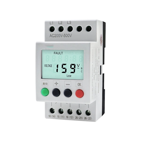
Welcome to our channel! In this video, we'll walk you through the process of wiring a home distribution box with a detailed connection diagram. more Welcome to our. Understanding the wiring diagram of an electrical panel box is essential for electricians and homeowners alike, as it allows them to troubleshoot any electrical issues, carry out repairs, or make additions to the system. What is Distribution Board? Distribution board. Hey, in this article we are going to see the Single Phase Distribution Box Wiring Diagram and Connection Procedure. A distribution board or distribution box is where the main power supply is distributed to multiple loads. And all the switching and protective devices are installed in the. That's why having a clear, detailed diagram of your home's distribution board wiring is essential. The diagram. Product Overview Renogy PMS1280 Smart Distribution Box is a centralized direct current (DC) power control hub specially designed for off-grid recreational vehicles, yachts, and motorhomes. The distribution box provides 12 circuit channels for load control as well as voltage and current detection.
[PDF]
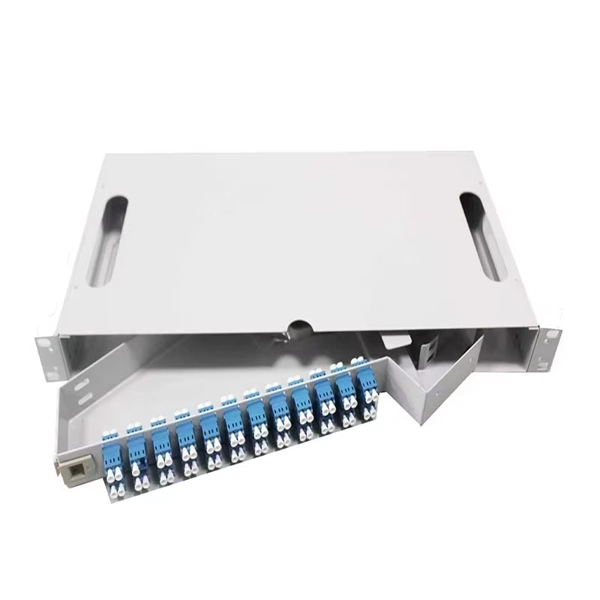
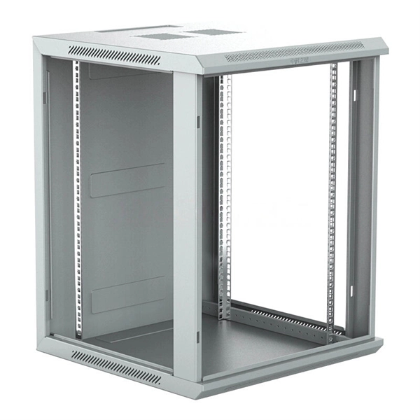
Rack Elevation or Server Rack Layout Software are simple tools to plan and document the cabling of your server cabinet. To make it even easier for you, we launched the free online Rack Planner. It helps you create a helpful rack diagram and keep your network tidy. Network cabinet cabling describes the structured connection and arrangement of all IT components in a server rack. The aim is a secure, maintainable and scalable operation of the network environment. Step-by-step guide: In this way, patch panels, switches, cable routing and documentation are. Creating a rack diagram is an important step to having sustainable good cable management in the network cabinet. Let's take a look at the essential components, selection criteria, and best practices for efficiency, order and protection of the network. Use cabinet screws to fix the network patch panel to the network cabinet. Note the wiring sequence on the patch panel when wiring, as T568A and T568B have different sequences. Wiring a server or network rack feels simple at first. Cables plug in, and devices turn on. Then problems appear. Slow speeds and tangled wires with card troubleshooting. Clean wiring prevents those issues before they start.
[PDF]
Roadside Telecommunications (RS-TC) Fiber Optic Cable Installation Adjusted Capital Cost Scatter Plot The data used to produce this cost plot are sourced from the ITS Sample Unit Costs Database. These cost data are obtained directly from a variety of sources. Buying fiber optic installation services involves several cost components, with total price influenced by length, location, and access. The main cost drivers include trenching or aerial deployment, materials, labor hours, and any required permits. This guide presents typical price ranges in USD to. Costs to run fiber optic cable vary by distance, trenching needs, cable type and labor rates. This guide outlines typical price ranges and what drives the total cost for U S buyers. Commercial building installations with 100-200 network drops generally range from $15,000 to $30,000. You should account for permit. Typically, per drop fiber cabling prices range from $250 – $1000 per drop depending on the type of fiber (OM2, OM3, OM4, or OM5), multi or single mode, PVC or plenum, average drop length, and also the number of fibers in each cable. Unit cost descriptions have not been.
[PDF]
In this step-by-step tutorial, we'll cover: ✅ Tools you need ✅ Safety precautions ✅ Mounting the box ✅ Wiring tips ✅ Final checks Perfect for beginners, DIYers, and electricians who want a clear installation guide. more Learn how to properly install an electrical. Electrical switch box wiring is a critical aspect of any electrical installation. The electrical panel box wiring diagram provides a visual representation of. A junction box provides a code-approved place to house wire connections, whether for outlets, switches, or splices. Here's how to install one. We may be compensated if you purchase through links on our website. It acts as a central connection point for various electrical wires, allowing for the easy distribution of electricity to different fixtures and devices. A properly installed and wired junction box ensures the safety and. Are you ready to master the skill of building electrical panels? This detailed guide provides an excellent base for beginners. Learn about the essential components of panels, such as the circuit breakers and fuses that safeguard against hazards. Then, delve into complex wiring configurations.
[PDF]
Simple 3-phase distribution board wiring diagram for home use, showing safe connection of power supply, breakers, neutral, and earth for residential electrical systems. Hey, in this article we are going to see the Three (3) Phase Distribution Board Wiring Diagram and Connection Procedure. The three-phase distribution board is used to distribute power to the three-phase loads and circuits such as three-phase motors, three-phase machinery, three-phase to. In a newly constructed residential area, a 10kV power line is introduced into the substation. After stepping down the voltage through the transformer's low-voltage side (0. The following is a detailed introduction about it: - **First-level Distribution. Utilities may have some control over and access to the energy stored in electric vehicles attached to the grid. ndards and conformity assessment activities in the United States. ANSI facilitates and promotes voluntary consensus standar rty or economic loss due to fire, electrical and related hazards. They deliver information and knowledge through more than 300 consensus codes and nspection to protect people.
[PDF]

One-line diagrams and detailed network data (lines, transformers, buses). Short-circuit models, including fault current calculations under various system configurations. Protective relay settings and coordination curves. Historical. presentation of protection and control relaying. The report will identify methodology behind these practices, present issues raised by the integration of microprocessor relays and the internal logic and external communication configurations, ying. Schematic diagrams of protection relays are essential tools for power engineers in the power generation, transmission, and distribution industry. This includes AC schematics and DC schematics and diagrams that prominently feature relaying. There are other equally important types of drawings that are not the subject. Power System Protective Relays: Principles & Practices Presenter: Rasheek Rifaat, P. Eng, IEEE Life Fellow IEEE/IAS/I&CPSD Protection & Coordination WG Chair Jacobs Canada, Calgary, AB rasheek. com IEEE Southern Alberta Section PES/IAS Joint Chapter Technical Seminar - November 2016. Recognized under 2(f) and 12 (B) of UGC ACT 1956 (Affiliated to JNTUH, Hyderabad, Approved by AICTE - Accredited by NBA & NAAC – 'A' Grade - ISO 9001:2015 Certified) Maisammaguda, Dhulapally (Post Via. Kompally), Secunderabad – 500100, Telangana State, India To introduce all kinds of circuit.
[PDF]
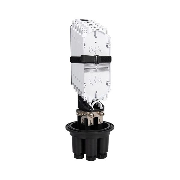
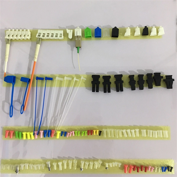
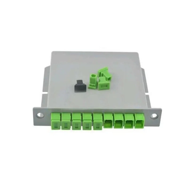
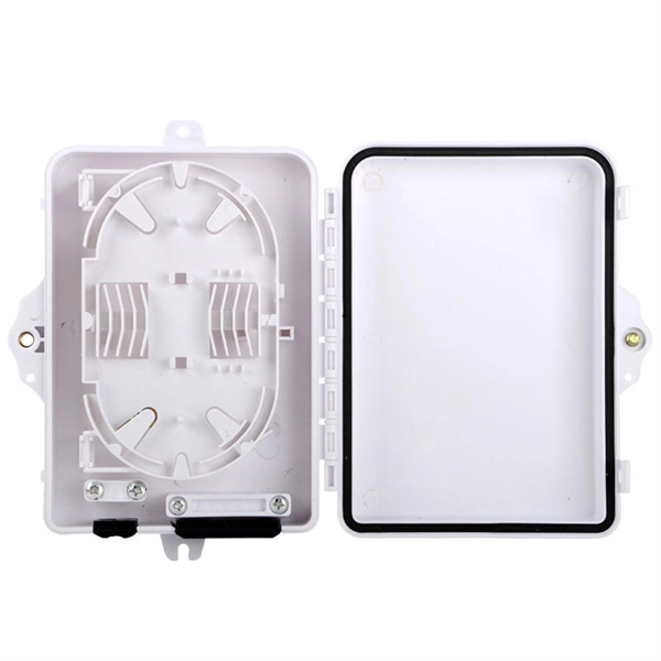
A fiber optic pigtail is a short length of optical fiber —typically 0. 5m to 2m—that has a factory-terminated connector on one end and bare fiber on the other end. The connector end is polished and tested under factory conditions, ensuring low insertion loss and high return loss. They are the bridge between fiber optic cables in the field and the equipment or patch panels that manage them. By combining factory-installed connectors with spliced bare fiber, pigtails ensure that network installers can create fast, reliable, and cost-effective terminations. Without pigtails. What is a Fiber Optic Pigtail, and What Is It Used For? Written by Ben Hamlitsch, trueCABLE Technical and Product Innovation Manager RCDD, FOI A fiber optic pigtail is a type of fiber optic cable with only one end that has a factory-terminated connector and the other end exposed as bare fiber. ) fitted on one end and the other end undressed (for connection through fusion or splicing) to the main fiber optic cable. It is usually suitable for field termination using a mechanical or fusion splicer. Compared with quick termination or epoxy and polish connections placed on the field. Fiber optic pigtail offers an optimal way to joint optical fiber, which is used in 99% of single-mode applications. This post contains some basic knowledge of fiber optic pigtail, including pigtail connector types, fiber pigtail classifications.
[PDF]
In telecommunications, an eye pattern, also known as an eye diagram, is an oscilloscope display in which a digital signal from a receiver is repetitively sampled and applied to the vertical input (y-axis), while the data rate is used to trigger the horizontal sweep (x-axis). It is so called because, for several types of coding, the pattern looks like a series of eyes between a pair of rails. It is a too. CalculationThe first step of computing an eye pattern is normally to obtain the waveform being analyzed in a quantized form. This may be done by measuring an actual electrical system with an oscilloscope of sufficient bandwidth,. Each form of baseband modulation produces an eye pattern with a unique appearance. The eye pattern of a signal should consist of two clearly distinct levels with smooth tra. Many properties of a can be seen in the eye pattern. applied to a signal produces an additional level for each value of the signal, which is higher (for pre-emphasis) or lower (for de-emp.
[PDF]
This AutoCAD DWG file includes a complete Single Line Diagram (SLD) of a Distribution Board, showing circuit breakers, wiring connections, and load distribution for lighting, power, and mechanical systems. An electrical panel box, also known as a breaker box or a distribution board, is a crucial component of any electrical system. It serves as a central hub for distributing electricity throughout a building, ensuring that power is delivered safely and efficiently to all the required locations. And all the switching and protective devices are installed in the. A distribution box is a key part of electrical systems in buildings. Inside, you'll find parts like circuit breakers and fuses that protect the system from problems like overloads and short circuits. Today, electrical systems are essential for homes and industries. Electrical Distribution board is used for controlling of utilization of power in the end point like as lighting circuit, power circuit and other equipment like as TV, fridge and airconditioning. The incomer supply is received from distribution panel. In this board, balance load is distributed as.
[PDF]
This guide will walk you through the essential steps to design and wire an efficient PLC control cabinet. We'll cover key topics like selecting components, cabinet layout, cooling, wiring, and safety to help you create a reliable and durable system. What is a PLC. Designing a plc cabinet takes more than just picking parts and wiring them up. You want every panel to meet strict safety requirements and deliver top efficiency for your automation projects. What is a PLC Control Cabinet? A PLC control cabinet plays a vital role in industrial automation by housing and. Electrical control panel wiring should be organized well or it can be unsafe or even hazardous. It is important that wiring be held together neatly using cable ties to ensure that everything is in an organized and neat order. It is advisable for everything to be tightly connected and there should. Construct control cabinets in a fraction of the time through simple manual wiring without tools: WAGO Push-in CAGE CLAMP ® Technology allows you to reduce costs, increase the safety of your application and reduce the time and effort for control cabinet wiring by up to 50 percent. With Smart. Before wiring, read the drawings carefully and understand the designer's intent. Do not rely solely on personal experience. If any discrepancy or ambiguity is found, confirm with the designer before starting work. Keep wiring order clear and verifiable. Wiring procedures should be simple and.
[PDF]
In this video, we'll walk you through the process of wiring a home distribution box with a detailed connection diagram. Whether you're an electrician or a DIY enthusiast, this guide will help you understand the basics of home electrical distribution. more Welcome to our channel! In this video. An electrical panel box, also known as a breaker box or a distribution board, is a crucial component of any electrical system. It serves as a central hub for distributing electricity throughout a building, ensuring that power is delivered safely and efficiently to all the required locations. And all the switching and protective devices are installed in the distribution box. Single Phase Distribution Box generally consists of Double Pole MCBs, Single Pole MCBs, and RCCBs. Single Phase wiring installation is the most common wiring in residential buildings. What is Distribution Board? Distribution board. The electrical service panel, often called a breaker box, acts as the central distribution point for all electricity entering a home. Its function is to safely divide the incoming high-amperage utility power into smaller, manageable branch circuits that supply power to lights, outlets, and.
[PDF]
The British Standard Wire Gauge, often referred to as the Standard Wire Gauge or simply SWG, is a unit used to denote (size) as defined by 3737:1964, a standard that has since been withdrawn. It is also known as the Imperial Wire Gauge or British Standard Gauge. Although its use has significantly declined, SWG sizes are still used for measuring the thickness of guitar strings and certain types of electrical.
[PDF]
This video shows real on-site footage of electrical installation, demonstrating safe and standardized wiring methods used by professionals. more Learn how to wire a distribution box step by step!. A distribution box, also known as a distribution board, electrical panel, or breaker box, is an enclosure that houses electrical components responsible for distributing electricity throughout a building. more Learn how to wire a distribution box step by step! This video shows real on-site footage of. In this video, we'll walk you through the process of wiring a home distribution box with a detailed connection diagram. Whether you're an electrician or a DIY enthusiast, this guide will help you understand the basics of home electrical distribution. What is Distribution Board? Distribution board. Connection method: Each switch takes a wire from the incoming point and connects it to the incoming end of the switch, or uses parallel connection to reduce the difficulty of wiring. Wiring Direction: Wiring between the main circuit breaker and each branch circuit breaker in the box generally. Understanding the wiring diagram of an electrical panel box is essential for electricians and homeowners alike, as it allows them to troubleshoot any electrical issues, carry out repairs, or make additions to the system. It takes the incoming power and safely distributes it to different circuits throughout your building. However, the key to.
[PDF]
This video shows real on-site footage of electrical installation, demonstrating safe and standardized wiring methods used by professionals. Description: The BSL is illustrated in a low-voltage distribution panel wiring diagram. It consists of three main components: the voltage measuring circuit, secondary circuit protection, and the energy metering circuit. (1) The voltage measurement circuit uses a voltage conversion switch SA and. Primary distribution systems consist of feeders that deliver power from distribution substations to distribution transformers. A feeder usually begins with a feeder breaker at the distribution substation. Many feeders leave substation in a concrete ducts and are routed to a nearby pole. At this. Explosion-proof distribution boxes, vital terminal distribution equipment in power systems, play a crucial role in controlling and protecting industrial electricity in hazardous environments. Given their ubiquity, let's delve into the installation and wiring of indoor distribution boxes today. more Learn how to wire a distribution box step by step! This video shows real on-site footage of. Connection method: Each switch takes a wire from the incoming point and connects it to the incoming end of the switch, or uses parallel connection to reduce the difficulty of wiring. Wiring Direction: Wiring between the main circuit breaker and each branch circuit breaker in the box generally.
[PDF]
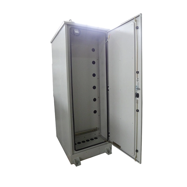
We specialize in built-to-spec electro-mechanical assembly and have more than 35 years of experience manufacturing custom cables, wiring harnesses, panels, box builds, test equipment and one-of-a-kind projects. Discover our selection of Multi-Connection Secondary Termination products. Our product experts are here to assist you. Get in touch with our team now. 3-Sixty Mfg is based in San Jose, California and offers custom assembly services since 2004. Made from fiberglass, metals, or plastics, they are designed to meet the most rigorous industry standards. A Cobra LockTM option can be added for. 200/600 Ampere | Single & Three Phase | 15, 25 & 35 KV | 2 Through 4-Way Junctions 14 or 12 Ga. G-90 Galvanized Steel. Powder TGIC Polyester Paint Finish, Munsell 7GY 3. Stainless Steel Ground Nuts. Conforms to IEEE C57. Positive Alignment. We offer both wedge wire and our proprietary Profile Bar construction methods for our screen products. Each has its unique advantages, and the choice depends on the application. Hendrick is the only American screen manufacturer that offers both Profile Bar and wedge wire solutions, allowing us to. Ratings are 800 - 6000 amp 600 volt, 3 phase 4wire, 3 phase 3wire, and 1 phase 3wire, NEMA 1/3R dual rated and Isc ratings of 85KA RMS symmetrical with no cable lashing required. (Please contact factory for higher Ratings) Cabinets are free standing and suitable for indoor or outdoor applications.
[PDF]