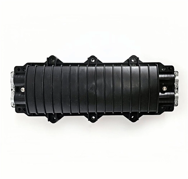
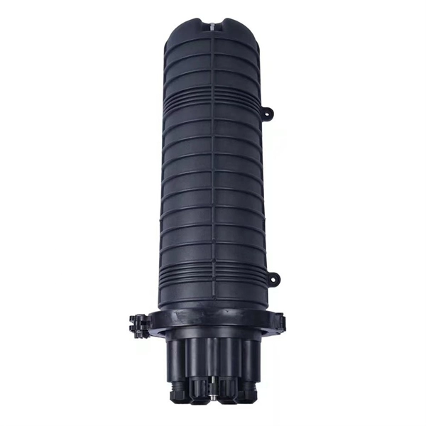
In network cabling, outdoor connections generally use fiber optic cables. When these optical fibers are installed or laid out, a Fiber Termination Box, or FTB, is used to distribute and protect the optical fiber link.
[PDF]
(1) The admissible load of a complete system depends on the system topography and the application parameters. Factors of influence are ambient temperature, air circulation, busbar load, distribution of busbar loa.
[PDF]
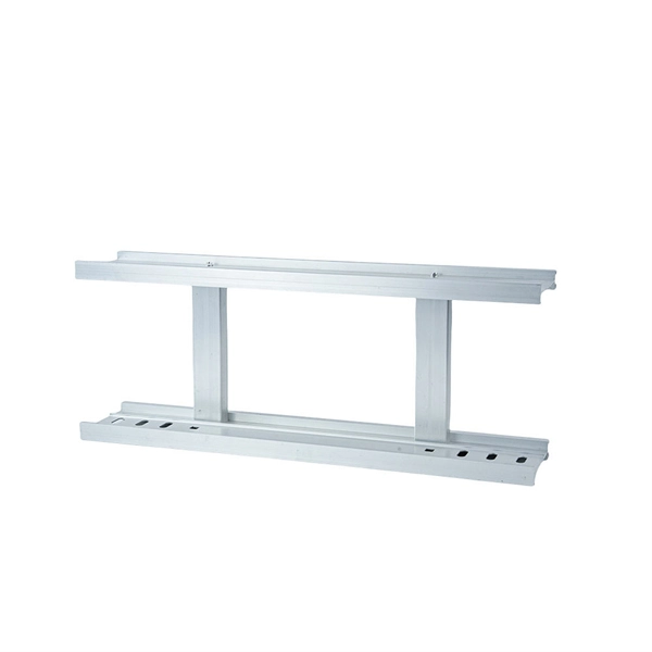
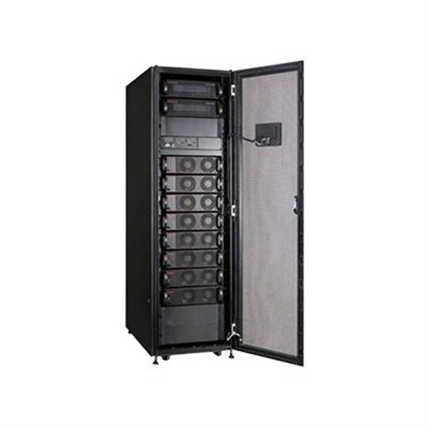
Rack Elevation or Server Rack Layout Software are simple tools to plan and document the cabling of your server cabinet. To make it even easier for you, we launched the free online Rack Planner. It helps you create a helpful rack diagram and keep your network tidy. Network cabinet cabling describes the structured connection and arrangement of all IT components in a server rack. The aim is a secure, maintainable and scalable operation of the network environment. Step-by-step guide: In this way, patch panels, switches, cable routing and documentation are. Creating a rack diagram is an important step to having sustainable good cable management in the network cabinet. Let's take a look at the essential components, selection criteria, and best practices for efficiency, order and protection of the network. Use cabinet screws to fix the network patch panel to the network cabinet. Note the wiring sequence on the patch panel when wiring, as T568A and T568B have different sequences. Wiring a server or network rack feels simple at first. Cables plug in, and devices turn on. Then problems appear. Slow speeds and tangled wires with card troubleshooting. Clean wiring prevents those issues before they start.
[PDF]
The standard requirement for wire is 1. 5 to 2 feet for each square foot of the home; however, it may change depending on the project scope, needs, and demands. Whether you're quoting a panel upgrade for a new build or wiring a multi-unit commercial space, the numbers on your estimate aren't just guesses—they're the difference between staying profitable and bleeding hours on change orders. This guide lays out what it really takes to build accurate. In May 2026 the estimated national average cost to Install Electrical Wiring starts at $302 - $365 per wiring run. Use our Cost Calculator for cost estimate examples customized to the location, size and options of your project. Set Project Zip Code Enter the. It's natural to wonder about the bottom line, and understanding the electrical wiring cost per foot is the perfect place to start. When installed by a professional, this cost typically lands somewhere between $3 and $12. Here are the five steps to create a competitive electrical estimate. Early preparation. In electrical projects, preparing a professional electrical quote is an essential yet often time-consuming task. Calculating material costs, labor fees, and profit margins for electrical projects can be challenging, especially when meeting client expectations or managing revisions. The kitchen and the laundry area are the most power-consuming parts of the house.
[PDF]
Wire color: The neutral wire is blue, and the color of the phase wire (A phase is yellow, B phase is green, and C phase is red) should meet the standard. Wire specification: Select the appropriate wire specification according to the circuit load. WARNING: Please be aware that the table below is a guide; a wire should never be identified by color alone. Wire color helps identify intent, not actual condition. Before handling any wire, always rely on testing with professional tools, not assumptions. Testing is the only reliable way to confirm. This guide describes wiring color codes, international standards, and main rules to keep in mind to work smarter and safer. The various colored wires that you can see when you look behind a switch or an outlet are not an accident, but rather a safety feature that is built in. For typical building AC circuits (commonly up to 600 volts nominal), the NEC specifies identification rules for grounded conductors (neutral), requirements. Electrical wiring color codes are a standardized system that tells electricians—and you—the specific job of every wire in the circuit. Getting this language right is the difference between a light that works and a dangerous situation involving short circuits, electrical shocks, or even fires. These color codes are used for electrical distribution systems, and while some are mandatory, others are optional. The lighting and socket circuits generally use.
[PDF]
This video shows real on-site footage of electrical installation, demonstrating safe and standardized wiring methods used by professionals. more Learn how to wire a distribution box step by step! This video shows real on-site footage of. An electrical panel box, also known as a breaker box or a distribution board, is a crucial component of any electrical system. It serves as a central hub for distributing electricity throughout a building, ensuring that power is delivered safely and efficiently to all the required locations. Proper grounding, insulation, and connection of wires are essential to maintain the integrity of the electrical system. Here are some key reasons why proper wiring is crucial in a 3 phase DB box: Prevention of Electrical Hazards: Proper wiring ensures that electrical currents flow smoothly and. Ensure safe placement: install in dry, accessible areas with good ventilation and at appropriate height (typically ~1. Whether you're a professional or a DIY enthusiast, understanding the correct procedure can prevent accidents and ensure optimal performance. This guide provides step-by-step. Hey, in this article we are going to see the Single Phase Distribution Box Wiring Diagram and Connection Procedure. And all the switching and protective devices are installed in the.
[PDF]
All wiring in hoistway and in equipment room shall be of a type identified by CEC 620. Please add appropriate notes. Separate branch circuits are needed for car lights, receptacle outlets, and ventilation. The purpose of this T/C is to clarify wiring that is permitted to be located in an elevator hoistway, machine/control room, or control space/room. Minimizing the need for. These requirements, found in Article 620 (part of Chapter 6, Special Equipment), are in addition to NEC Chapters 1-3, which stipulate general wiring protocols applicable in most residential, commercial and industrial venues. The code exempts some fairly broad areas where compliance is not expected. In Oregon, Raceways and conduits for the connection of elevator devices shall only enter the machine room to the extent necessary to connect the devices attached thereto. 37 covers wiring in hoistways, machine rooms, control rooms, machinery spaces, and control spaces related to the. By General Contractor / Owner Each home elevator requires five (5) items from your Electrician and Telecommunications Contractor(s). They are as follows: One (1) GFI Outlet. One (1) Light Fixture (with protective cover over bulb) with wall switch. One (1) Live Land Based Phone Line with pigtail. Main Power - 10/3 with Ground (min. 6”) pigtail connected to house 30 Amp dedicated circuit. 240VAC for LLH REQUIRES neutral. One (1) GFI Outlet separate from #2 elevator (120VAC) circuit.
[PDF]
A neat, well-organized subpanel bundles wires to conserve space and improve access. Ideally, wire groups are installed in layers and wires are bent at right angles to buses or breakers. Label short sheathing sections (slugs) to indicate which circuits wires serve. Choose the right box based on environment (indoor/outdoor), load capacity, and durability. Check for proper IP/NEMA ratings and material quality. Ensure safe placement: install in dry, accessible areas with good ventilation and at appropriate height (typically ~1. Practice good wiring: secure. Box installation: Make sure that Distribution box has been correctly installed and fixed. Material preparation: Prepare the required circuit breakers, wires, wiring ties and other materials, and ensure that they meet the design drawings and installation requirements. And all the switching and protective devices are installed in the. Wiring distribution panels serve as the central hub and nerve center, routing power from the main service feed to multiple circuits. When setting up such a significant component of industrial, commercial, and utility applications, it's essential to get everything right. Labeling cables at outlets is.
[PDF]

This video shows real on-site footage of electrical installation, demonstrating safe and standardized wiring methods used by professionals. However, exposure to weather, frequent relocation, rough use and other condi-tions not normally encountered with conventional wiring systems necessitate special consideration not require in other applications or in completed structures. The. A distribution box is the heart of any electrical system. It takes the incoming power and safely distributes it to different circuits throughout your building. Whether in a home or an industrial facility, this box keeps your electrical setup organized, functional, and efficient. However, the key to. Temporary power systems are essential for construction projects, yet they often introduce serious safety risks. Loose wiring, exposed connectors, and unstable electrical connections can cause shocks, equipment failures, or costly downtime. This article examines how modern portable power cabinet. Conductors entering boxes, cabinets, or fittings. Conductors entering boxes, cabinets, or fittings shall be protected from abrasion, and openings through which conductors enter shall be effectively closed. Covers and. Whether you are an electrical contractor or a construction brigade, knowing how to properly and safely install distribution boxes is the basis of ensuring the safe operation of the entire system. This article details the process of installing them, which helps you comprehend distribution boxes.
[PDF]
wiring and junction box is designed for safely housing and protecting electrical wiring in outdoor settings. Its weather-resistant construction shields against rain, sleet, and snow, making it ideal for residential, commercial, and industrial applications. The Southwire NEMA 3R outdoor enclosure 6 in. The single service 2-gang Outdoor Ground Box is made from a UV rated nonmetallic material and has been designed to withstand the harsh outdoor environments. The gray. IP 24NEMA 3RMild Steel painted ASA 61 Gray The 1300 CH are specially designed for outdoor wiring installations in order to protect against rain, sleet and snow. Boxes can also be used indoors to protect against dripping water. The box and cover are made of high quality 14 GA or 16 GA steel. Built for rugged reliability, these enclosures are. MAX-SHIELD DURABILITY: Built with high-impact ABS and UV-stabilized polycarbonate. Engineered to resist cracking, yellowing, and structural fatigue in extreme sub-zero or high-heat environments. IP67 WATERPROOF RATING: Precision-molded gaskets provide a vacuum-tight seal. Guaranteed protection. Electrical enclosures allow you to keep your electrical components clean, dry, and protected while also keeping the components accessible. Shop our large.
[PDF]
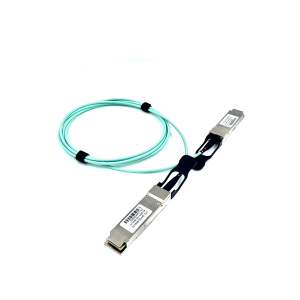
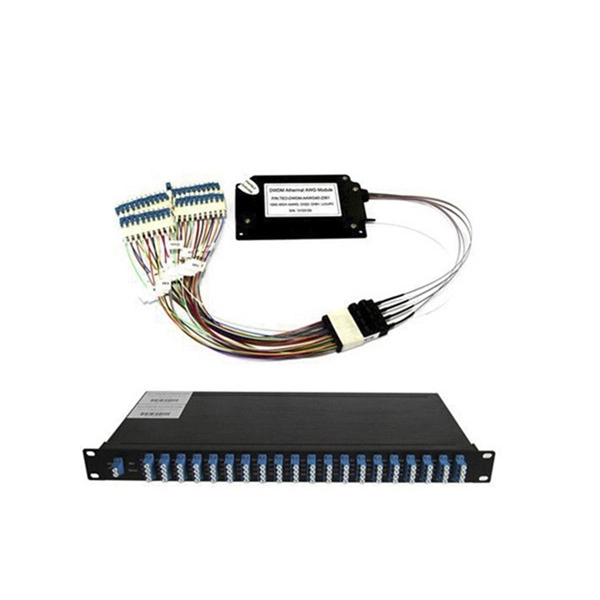
The other side of the pigtail is open and is connected to a fiber optic cable. This creates a stable and reliable connection between network equipment. They are the bridge between fiber optic cables in the field and the equipment or patch panels that manage them. By combining factory-installed connectors with spliced bare fiber, pigtails ensure that network installers can create fast, reliable, and cost-effective terminations. DINTEK supplies this equipment, but the pigtails can also be. In the intricate ecosystem of fiber optic networks, two components play a critical role in ensuring seamless connectivity: patch cords and pigtails. A fiber optic pigtail is a type of fiber optic cable with only one end that has a factory-terminated connector and the other end exposed as bare fiber. When compared to field-installed rapid. Today, I'll show you how to pick the right patch cord or pigtail — step by step. You plug it into a switch, router, or patch panel. It's ready to use out of the box. A pigtail is for splicing.
[PDF]
For a three-way switch, two pigtails are generally connected to the common terminal: one for the incoming hot wire and one to extend the power to another device if needed. A simple switch does not need a neutral since the switch is interrupting the power feed only. Sometimes the power is run to the fixture box first and then a single 2 wire cable is brought down. In that instance. Traditional switches often require the home's circuit wires to be looped directly onto screw terminals, which can become a point of failure over time. Currently there are 10 ground wires spliced together if you include the 3 pigtails going to the switches. I haven't been able to open everything up and diagram. Each power conductor counts as 1. Pigtails do not count. 2nd. According to the National Electrical Code (NEC – United States) each item depending on the gage of wire Now take the number you came up with in the 1st column and multiply it by the cubic inch required [listed in 2nd column] for the. Pigtails act as bridges, allowing you to connect several wires to a single point without overloading connections. Professionals often prefer this method because it isolates issues, protecting downstream circuits from cascading failures. Why does this matter? Modern systems demand precision. For instance, if your circuit includes multiple wires feeding into a single outlet, pigtails create a reliable connection between the device and the circuit wires. This process prevents.
[PDF]
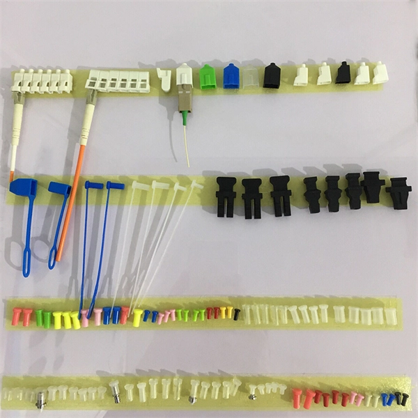
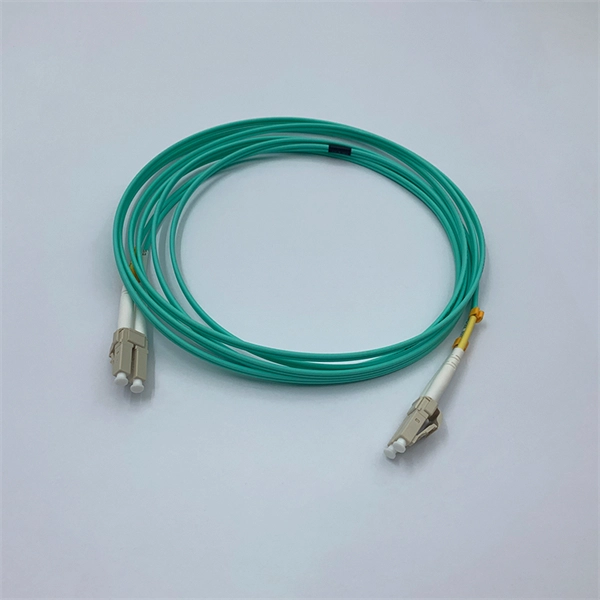
Transmission Modes: Fiber pigtails can be single-mode or multimode. Single-mode fibers transmit one signal per fiber and are used for long-distance transmission. Choosing between single-mode and multimode fiber optic pigtails is one of the most important decisions in network design. What Is Single-Mode Fiber? What Is Multimode Fiber? Choose single-mode pigtails if: Choose multimode pigtails if: Browse available options: Need help? We're available at. Understanding the differences between single-mode and multi-mode fiber pigtails is crucial for selecting the right type for data centers, telecommunications, FTTH (Fiber to the Home) installations, or enterprise networks. Choosing the right pigtail directly impacts signal transmission distance. Fiber optic pigtails play a critical role in modern optical networks, serving as the interface between optical fibers and active or passive devices through fusion splicing. Understanding the compatibility constraints prevents costly downtime and troubleshooting. On the other hand. Knowing how to tell the difference between single mode and multimode fiber is crucial for network efficiency; the core distinction lies in the fiber's core diameter and how light travels through it, affecting bandwidth, distance, and cost. Fiber optic cables transmit data as pulses of light through.
[PDF]
Use pigtails when connecting multiple wires to a single terminal, upgrading outlets or switches, or managing crowded electrical boxes. Pigtails play a crucial role in ensuring safe and efficient connections within electrical systems, especially when dealing with multiple wires or limited space. Understanding what a pigtail is and how it works can make your wiring projects smoother and safer. ” This method is especially useful when connecting wires to devices such as switches, outlets, and junction boxes, allowing. Proper using pigtails breaks this chain. By creating independent pathways, technicians isolate problems without shutting down complete circuits. Commercial buildings using this method report 83% faster troubleshooting times. The National Electrical Code mandates continuous neutral connections in. Optical fiber pigtails are short optical fibers used to connect fiber optics with other equipment (such as optical modules, splitters, etc. ), typically used in fiber optic networks. With advantages such as low insertion loss, high return loss, good interchangeability, and repeated plugging. A pigtail in electrical wiring is a short length of conductor used to transition from a bundle of multiple circuit wires to a single termination point, such as a device terminal or fixture connection. This technique is often employed when three or more wires need to be joined, ensuring that the.
[PDF]
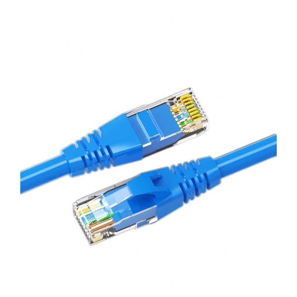
Learn the key difference between pigtail and jumper cables: only one end of a pigtail connects, while both ends of a jumper feature connectors. Similar to coaxial cable, but without mesh shielding, for jumper. When it comes to fiber optics, we naturally think of patch cords and pigtails. Usually people don't know the difference between the two. Let's find out together. Carrier-grade single-mode fiber patch. The Fiber Optic Patch Cord, also referred to as a fiber optic patch cable or fiber jumper, is a specialized cable designed for transmitting data signals using light waves in fiber optic communication systems. It is worth noting that fiber pigtails and patch cords are not the same concept. The main difference between fiber optic patch cords and fiber optic pigtails is that only one end of the fiber optic pigtail has an active connector, and both ends of. Jumper cables and portable jumper boxes are both tools used to revive a vehicle with a dead battery, but they have distinct differences despite sharing a similar end-goal. And with a plethora of purchasable options in both camps, it can be difficult to decide which way to spend your pretty pennies.
[PDF]