In this guide, we will explore the significance of connecting PVC conduit to electrical boxes and provide you with a step-by-step process to accomplish this task effectively. Whether you're dealing with rigid metal conduit (RMC), PVC, or flexible conduit that's already in place, it can be removed or replaced, but there's no magic wand. You'll need to consider the type of conduit, the installation method, and. Electrical conduit fittings form the outer covering for most electrical wiring from one point to the next. They shield the wires from the external environment so as to make the wire last longer and also to keep humans and pets safe from electric shocks or other such vulnerabilities. The breaker box, or service panel, serves as the central distribution point, housing the circuit breakers that protect individual circuits from overcurrent conditions. Connecting made easy: How to effortlessly connect PVC conduit to electrical boxes! Installing electrical systems just got simpler with Ledes' seamless conduit connections! 💡. Firstly, it. Why Publish? How to Repair and Remove Conduit for Electric Wires: Let me teach you how to easily repair and remove conduit for electric wires. For the full guide and more tips read the post in 123 Do It Yourself blog: com/2014/01/22/22/.
[PDF]
The standard requirement for wire is 1. 5 to 2 feet for each square foot of the home; however, it may change depending on the project scope, needs, and demands. Whether you're quoting a panel upgrade for a new build or wiring a multi-unit commercial space, the numbers on your estimate aren't just guesses—they're the difference between staying profitable and bleeding hours on change orders. This guide lays out what it really takes to build accurate. In May 2026 the estimated national average cost to Install Electrical Wiring starts at $302 - $365 per wiring run. Use our Cost Calculator for cost estimate examples customized to the location, size and options of your project. Set Project Zip Code Enter the. It's natural to wonder about the bottom line, and understanding the electrical wiring cost per foot is the perfect place to start. When installed by a professional, this cost typically lands somewhere between $3 and $12. Here are the five steps to create a competitive electrical estimate. Early preparation. In electrical projects, preparing a professional electrical quote is an essential yet often time-consuming task. Calculating material costs, labor fees, and profit margins for electrical projects can be challenging, especially when meeting client expectations or managing revisions. The kitchen and the laundry area are the most power-consuming parts of the house.
[PDF]
In this step-by-step tutorial, we'll cover: ✅ Tools you need ✅ Safety precautions ✅ Mounting the box ✅ Wiring tips ✅ Final checks Perfect for beginners, DIYers, and electricians who want a clear installation guide. more Learn how to properly install an electrical. Electrical switch box wiring is a critical aspect of any electrical installation. The electrical panel box wiring diagram provides a visual representation of. A junction box provides a code-approved place to house wire connections, whether for outlets, switches, or splices. Here's how to install one. We may be compensated if you purchase through links on our website. It acts as a central connection point for various electrical wires, allowing for the easy distribution of electricity to different fixtures and devices. A properly installed and wired junction box ensures the safety and. Are you ready to master the skill of building electrical panels? This detailed guide provides an excellent base for beginners. Learn about the essential components of panels, such as the circuit breakers and fuses that safeguard against hazards. Then, delve into complex wiring configurations.
[PDF]
Wire color: The neutral wire is blue, and the color of the phase wire (A phase is yellow, B phase is green, and C phase is red) should meet the standard. Wire specification: Select the appropriate wire specification according to the circuit load. WARNING: Please be aware that the table below is a guide; a wire should never be identified by color alone. Wire color helps identify intent, not actual condition. Before handling any wire, always rely on testing with professional tools, not assumptions. Testing is the only reliable way to confirm. This guide describes wiring color codes, international standards, and main rules to keep in mind to work smarter and safer. The various colored wires that you can see when you look behind a switch or an outlet are not an accident, but rather a safety feature that is built in. For typical building AC circuits (commonly up to 600 volts nominal), the NEC specifies identification rules for grounded conductors (neutral), requirements. Electrical wiring color codes are a standardized system that tells electricians—and you—the specific job of every wire in the circuit. Getting this language right is the difference between a light that works and a dangerous situation involving short circuits, electrical shocks, or even fires. These color codes are used for electrical distribution systems, and while some are mandatory, others are optional. The lighting and socket circuits generally use.
[PDF]
This video shows real on-site footage of electrical installation, demonstrating safe and standardized wiring methods used by professionals. more Learn how to wire a distribution box step by step! This video shows real on-site footage of. An electrical panel box, also known as a breaker box or a distribution board, is a crucial component of any electrical system. It serves as a central hub for distributing electricity throughout a building, ensuring that power is delivered safely and efficiently to all the required locations. Proper grounding, insulation, and connection of wires are essential to maintain the integrity of the electrical system. Here are some key reasons why proper wiring is crucial in a 3 phase DB box: Prevention of Electrical Hazards: Proper wiring ensures that electrical currents flow smoothly and. Ensure safe placement: install in dry, accessible areas with good ventilation and at appropriate height (typically ~1. Whether you're a professional or a DIY enthusiast, understanding the correct procedure can prevent accidents and ensure optimal performance. This guide provides step-by-step. Hey, in this article we are going to see the Single Phase Distribution Box Wiring Diagram and Connection Procedure. And all the switching and protective devices are installed in the.
[PDF]
In this informative tutorial, we will guide you through the step-by-step process of wiring a 3 phase distribution DB box. Whether you are an electrician, a DIY enthusiast, or simply curious about electrical installations, this video is perfect for you. A distribution board, also known as a DB box, is like the central hub of an electrical system. It contains multiple circuit breakers and connects various electrical circuits to ensure. NO. While a single phase distribution board is capable of managing just one type of power source, the three phase distribution board is designed to manage multiple sources. This makes it an invaluable tool for. Three-phase system can be described as the common method of alternating current power generation, transmission, and distribution. In this system, the current will pass through the three wires, and there will be one neutral wire for passing the fault current to the earth. Three-phase distribution boards are used in large factories, buildings, manufacturing units.
[PDF]
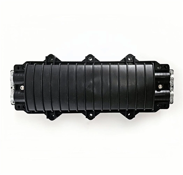
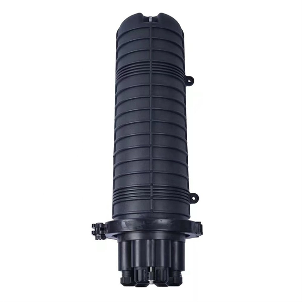
In network cabling, outdoor connections generally use fiber optic cables. When these optical fibers are installed or laid out, a Fiber Termination Box, or FTB, is used to distribute and protect the optical fiber link.
[PDF]
(1) The admissible load of a complete system depends on the system topography and the application parameters. Factors of influence are ambient temperature, air circulation, busbar load, distribution of busbar loa.
[PDF]
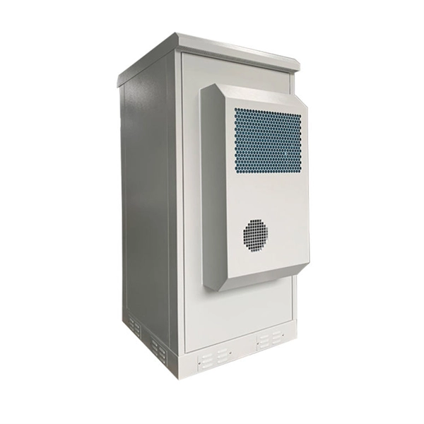
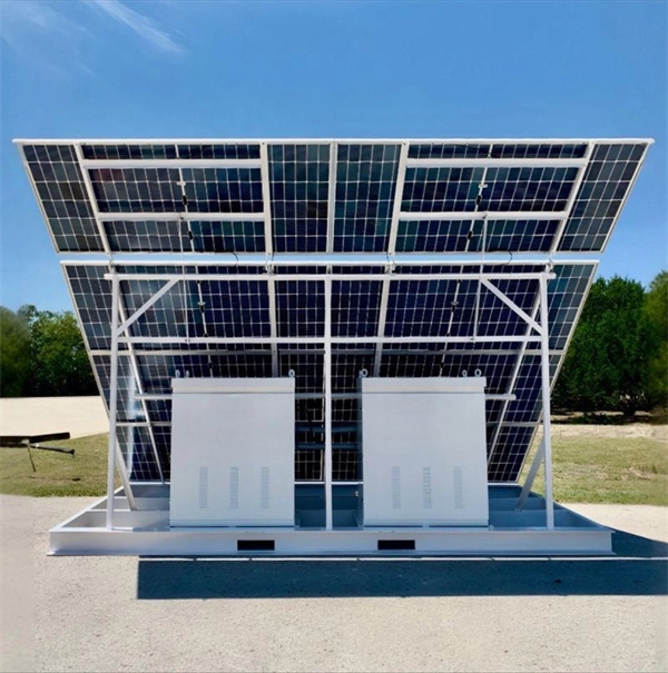
wiring and junction box is designed for safely housing and protecting electrical wiring in outdoor settings. Its weather-resistant construction shields against rain, sleet, and snow, making it ideal for residential, commercial, and industrial applications. The Southwire NEMA 3R outdoor enclosure 6 in. The single service 2-gang Outdoor Ground Box is made from a UV rated nonmetallic material and has been designed to withstand the harsh outdoor environments. The gray. IP 24NEMA 3RMild Steel painted ASA 61 Gray The 1300 CH are specially designed for outdoor wiring installations in order to protect against rain, sleet and snow. Boxes can also be used indoors to protect against dripping water. The box and cover are made of high quality 14 GA or 16 GA steel. Built for rugged reliability, these enclosures are. MAX-SHIELD DURABILITY: Built with high-impact ABS and UV-stabilized polycarbonate. Engineered to resist cracking, yellowing, and structural fatigue in extreme sub-zero or high-heat environments. IP67 WATERPROOF RATING: Precision-molded gaskets provide a vacuum-tight seal. Guaranteed protection. Electrical enclosures allow you to keep your electrical components clean, dry, and protected while also keeping the components accessible. Shop our large.
[PDF]

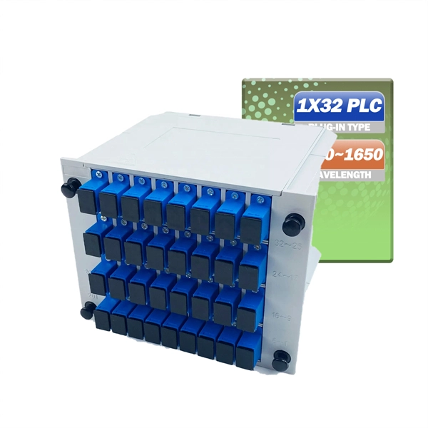
Optical splitters enable a signal on an optical fiber to be distributed among two or more fibers. Since fiber splitters contain no electronics nor require power, they are an integral component and widely used in most fiber-optic networks. A fiber optic splitter is a passive optical component that divides a single incoming optical signal into two or more outgoing signals, or combines multiple incoming signals into one. Unlike active devices (which require power), splitters operate without electricity, relying solely on the physics of. Optical cables, also known as fiber optic cables, consist of thin strands of glass or plastic fibers surrounded by a protective casing. These fibers transmit data as light signals, which are converted into electrical signals at the receiving end. The benefits of optical cables are numerous. A fiber-optic splitter, also known as a beam splitter, is based on a quartz substrate of an integrated waveguide optical power distribution device, similar to a coaxial cable transmission system. Its primary role is in Passive Optical Networks (PON), which are the foundation of. A fiber broadband provider typically determines and overall split ratio for the network, such as 1x32 or 1x64, and uses combinations of splitters to meet that ratio with each PON port. 1x32 splits were common in North America for G-PON architectures. As XGS-PON continues to be adopted, some service.
[PDF]
Summary : Fiber optic color codes are crucial for efficient, accurate, and reliable network installations. This guide explains how standardized fiber strands, cable jackets, connectors, and MPO systems simplify identification, prevent mismatches, and maintain signal. Tired of sorting poorly colored fibers? WolonFiber's 12-Color Fiber Optic Pigtail Packs are manufactured strictly to the TIA-598-C standard with vibrant, easy-to-identify colors. Perfect for fast, error-free termination in your ODF or splice closures. Following industry. You'll learn how to identify single-mode vs. multimode at a glance, trace individual strands in a 144-fiber bundle, and avoid the critical error of mixing connector types. In fiber optics, color isn't for decoration; it's a critical safety and efficiency tool. The TIA-598 standard (specifically. While labeling text offers specific details, color-coding makes it easy to identify cable uses or zones. In accordance with TIA-598-D standards fiber optic cables are based on the standard colors for jackets in single-mode: yellow, aqua/orange for multimode. 3 Create your own standards using colored.
[PDF]
The optical fibre sensors are divided into two categories: thrubeam and reflective. The thrubeam type comprises a transmitter and a receiver. The reflective type, which is a single unit, is available in 3 types: parallel, coaxial, and separate. The fibre optic sensor has an optical fibre connected to a light source to allow for detection in tight spaces or where a small profile is beneficial. The light beam travels through the core by. Fiber optic sensors are prevalent in various applications, from computers and printers to motion detectors. For instance, when a printer or copier door is open, light falls on the sensor, stopping the machine for safety. Fiber optic sensors use light properties to detect and measure physical quantities such as temperature, pressure, and displacement. Depending on the application scenario, different. Functional (all optical fiber type) optical fiber sensor Using optical fibers (or special optical fibers) with sensitivity and detection capabilities for external information as the sensor element, the sensor combines "transmission" and "sensation". During operation, the light source enters the optical modulation region through the incident fiber. The physical quantity to be measured (such as.
[PDF]

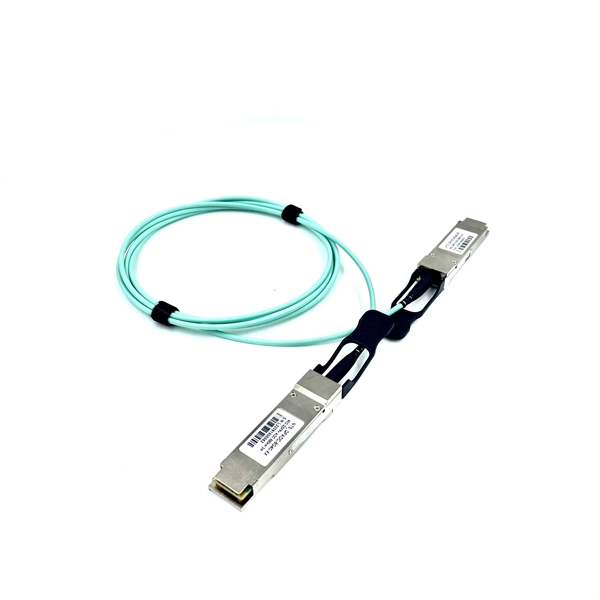
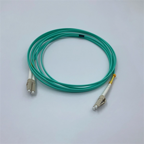
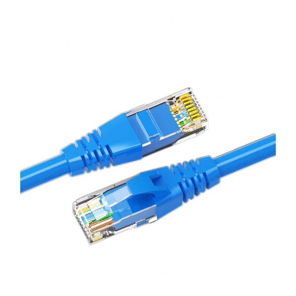
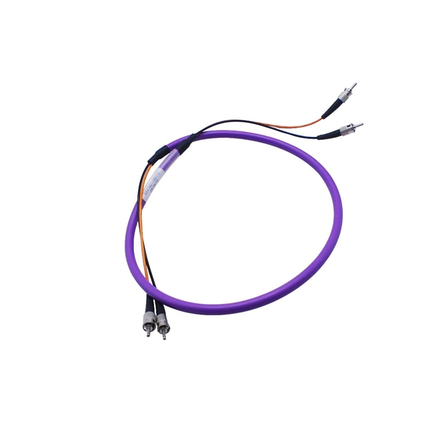
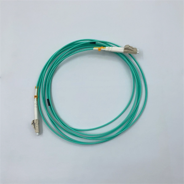
The most commonly used patch cable connectors today include FC, ST, SC, LC, MTRJ, and MPO connector types, as well as newer very small-form-factor (VSFF) CS, SN, and MDC connectors used in high-density, high-speed duplex data center environments. This guide will help you quickly understand the main types of fiber patch cords and how to choose the right solution for your project – and how ZION can support you with stable quality, flexible customization and global supply. What Is a Fiber Optic Patch Cord? A fiber optic patch cord (fiber. An optical fiber patch Cable is a jumper wire used to connect from equipment to an optical fiber cabling link, and it is usually used for the connection between an optical transceiver and a terminal box. It is widely applied in fields such as optical fiber communication systems, optical fiber. Fiber optic patch cords, also known as fiber optic patch cables or fiber jumpers, are indispensable components in modern optical networks. They act as the critical link for interconnecting devices like optical switches, servers, and distribution frames. Behind its slender appearance lies the fusion of core types, connector types, and polish levels, each chosen for a specific application. It is composed of fiber optic cable and fiber connector that fixed at both ends of optical cable, has been widely used in various fields such as fiber optic.
[PDF]
This document provides a comprehensive technical overview of the Ring Main Unit (RMU), serving as a reference for power system design, selection, and maintenance. Ring Main Units (RMU s) and Medium Voltage (MV) Switchgear are crucial in MV power distribution. Globally, they each hold about half the market share. MV switchgear handles primary distribution for large industrial facilities and grid infrastructure. RMUs, however, shine in secondary distribution. RMUs are commonly used in secondary distribution systems, particularly in urban areas, industrial complexes, and commercial. Scope of Application: The Ring Main Unit (RMU) is a compact switchgear device used in medium-voltage power distribution systems (typically 10kV–35kV). Some of the key features of the RMU includes SF6 gas insulation, compact and modular construction, integral protection system, fully extendable options. SFA-RM units are designed for supplying reliable energy, protecting electrical equipment in secondary distribution networks up to 17. Their compact design makes them suitable for various network applications such. Loading. Company Introduction:The New Concept Electric Inc. (NCE) was founded in October 2001, with a registered capital of 57 million Yuan. The company now covers an area of 77, 601 square meters (116 acres), and has a building area of 80, 451 square meters.
[PDF]
The primary function of a feeder wire is to facilitate bulk power transfer from a central source to a subpanel or a secondary distribution center. An example is the large cable running from the main service panel to a subpanel in a detached garage, basement, or workshop. A main panel and a sub-panel are both important components of an electrical distribution system. It is usually located where the main electrical service enters the building, often on an. Main feeder wires are the arteries of a building's electrical system, designed to safely and efficiently transport a large volume of power from the service entrance to secondary distribution points. They form the backbone of the electrical distribution network, handling the substantial current. An electrical sub panel, also known as a sub distribution board or sub circuit breaker panel, is a smaller secondary panel connected to the main electrical panel in a building. It serves as an extension of the main electrical panel to distribute power to different areas or circuits within a. Distribution board is a safe system designed for house or building that included protective devices, isolator switches, circuit breaker and fuses to safely connect the cables and wires to the sub circuits and final sub circuits including their associated Live (Phase) Neutral and Earth conductors. The distribution box acts as the center of power distribution, distributing electricity to all connected devices.
[PDF]