Recommendation ITU-T G. 654 describes the geometrical, mechanical and transmission attributes of a single-mode optical fibre and cable which has the zero-dispersion wavelength around 1300 nm wavelength, and which is loss-minimized and cut-off wavelength shifted at around the 1550 nm. Recommendation ITU-T G. 649 Optical fibre cables G. 659 Characteristics of optical components and subsystems Characteristics of optical systems G. 679. In recent years, a new type of G. E optical fibre has started to be used in some long-distance trunk lines, and has achieved better results. 654 fibre In the mid-1980s, in. As a leading fiber optic manufacturer with 21 years of experience, GL FIBER specializes in producing high-performance G. C, for long-haul and high-speed networks. Below, we explain the technical differences between these two fiber types to help you choose the. uous requirements for higher capacity optical transmission systems. To support these high capacity systems in terrestrial backbone networks, low attenuation and large core area fibers compliant with Recommendation ITU-T G 654. E were introduced and have been extensively deployed worldwide. For this protective layer, Sumitomo Electric utilizes a dual-layer acrylate coating structure. The precisely controlled coating diameters and the exceptional.
[PDF]
Fiber optic cables are perfect for long-distance applications. They can carry information over very long distances with very little signal loss. Additionally, fiber optic cables are not affected by electromagnetic i.
[PDF]
Attenuation in fiber optics is the gradual loss of light signal strength as it travels through a fiber cable. It's measured in decibels per kilometer (dB/km), and it determines how far a signal can travel before it becomes too weak to read. A standard single-mode fiber operating at 1550 nm loses. Optical Signal Attenuation is the single greatest factor limiting the distance and performance of your network. Understanding it is crucial for anyone involved in data centers, telecommunications, or enterprise networking. This guide will demystify signal loss, explore its causes, and show you how. As the distance light travels through an optical fiber increases, the light's strength decreases; this phenomenon is known as “fiber attenuation. ” It is also known as fiber loss or signal loss. This is a rather advanced discussion concerning the field of optical fiber. Optical fiber is our first. The attenuation is a telecommunication word which refers to reduction within signal strength. This can occur while transmitting signals over lengthy distances. It can be calculated in dB (decibels) in terms of voltage. In this blog, we'll explore what attenuation is, what. Optical fiber technology enables rapid data transmission over vast distances by guiding light signals through thin strands of glass.
[PDF]
This involves splicing the fiber drop cable to the fiber optic termination box, which is usually located on the outside of your house. Next, use a fusion splicer to splice the cable to the connector . For the Corning FASTACCESS fiber optic cable, I will show you how to remove the jacket and prep the cable for terminations. Think of it as the equivalent of connecting the dots in a complex puzzle; without proper termination, the whole system can break down. The fiber termination box is an interface between the fiber cable from the line side and the pigtails to be passed to the fiber distribution frame. A fiber pigtail is a specific hardware connection used for cable termination. Thus, a fiber termination box is used to terminate the optical fiber. Work with our experts to build the best solution for your environment. Our team will make sure the configuration is tailored to your needs and will provide a detailed quote. Email us using the Request a Quote below, or give our team a call. Additionally, you will need a fiber optic termination box, a drop cable, a messenger wire, and various connectors, including SC/APC, LC/APC, or ST/APC connectors, depending on your service provider. It is imperative that certain procedures be followed in the handling of these cables to avoid damage and/or limiting their usefulness. The information contained in this manual should serve as a guide to proper.
[PDF]
The Telecommunications Regulatory Agency (ART) announces that it has received directives from the government to conduct an operational audit of the national fiber optic network. MTN GlobalConnect and CAMTEL have joined forces to establish a strategic partnership that will see the commercialisation of four submarine cables in the West and Central sub-region of Africa. The partnership will improve connectivity in Cameroon and support the increasing demand for internet. CAMTEL gets big gov't support to boost optical fibre network. This decision follows a “continuous deterioration in the quality of mobile electronic communication services provided by. Cameroon has long been presented as a hub in terms of telecom infrastructure in the Central African sub-region. The country is connected to five optical fiber submarine cables (SAT3, WACS, ACE, SAIL, and NCSCS). Yet it makes very little use of this equipment to develop its telecoms sector, as well. National and international connectivity, secure data centres, and reliable interconnections for operators, businesses, and institutions. 24/7 performance, availability, and resilience.
[PDF]
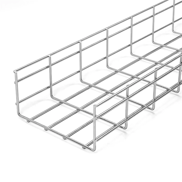
For such cables, we recommend using at least a 1. 5-inch conduit, and sometimes a 2-inch conduit may be necessary. It's important to consider not only the rigidity of the jacket but also the breakout point of the assembly, where the strands exit the jacket and are encased in. For such cables, we recommend using at least a 1. Selecting the appropriate conduit size is crucial and depends on the type of jacket on your cable assembly and the. Premise innerduct is a flexible, non-metallic, corrugated raceway that has long been an essential conduit system for protecting fiber optic cables installed throughout telecommunications spaces and pathways. Conduit also facilitates cable management and ease of maintenance. With these assemblies we mention in this article, the widest point. This calculator will allow you to find the fill ratio using one, two, or three cables within the conduit. If you only have one cable for your conduit, please use only the first cable diameter field. Once the fill ratio calculator is computed, the program tells you if it falls within Corning's. Calculation Method 1 – Calculate the minimum conduit size required for a specific number of cables. This is particularly useful when planning an installation. (Equation 1 below) Calculation Method 2 – Calculate the maximum number of cables that can be installed in a conduit of a known size. Next, select the type of conduit you are specifying. " To determine the size of.
[PDF]
This article provides a comprehensive exploration of the technology, including its advantages, working principles, application range, and system parameters. Distributed Temperature Sensing (DTS) systems provide temperature information for accurate thermal monitoring, fire detection, and condition assessment by utilizing standard fiber optic cables. These fiber optic systems precisely measure the temperature profile of an asset by interpreting the. Fiber sensing technology has emerged as a game-changer in this domain, offering unparalleled capabilities for real-time monitoring and early detection of potential issues. It's become so useful that in many cases it has become mandatory to include fiber-sensing-based monitoring for new pipelines. A fiber optic temperature sensor is a temperature measurement device that uses optical fibers as the sensing medium. Unlike traditional electrical temperature sensors (e., thermocouples, RTDs), fiber optic sensors offer significant advantages such as immunity to electromagnetic interference. As the name suggests these sensors employs fiber optics technology to function. Advances in optoelectronics and associated signal processing have enabled the development of optical fibre distributed sensors with maximum ranges of several tens of kilometres. The DTS system's ability to offer continuous temperature measurements over tens of kilometers with high spatial and temperature resolution has.
[PDF]
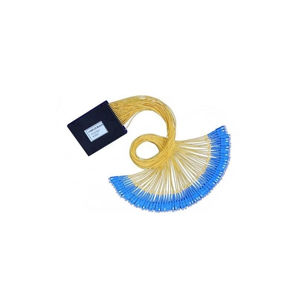
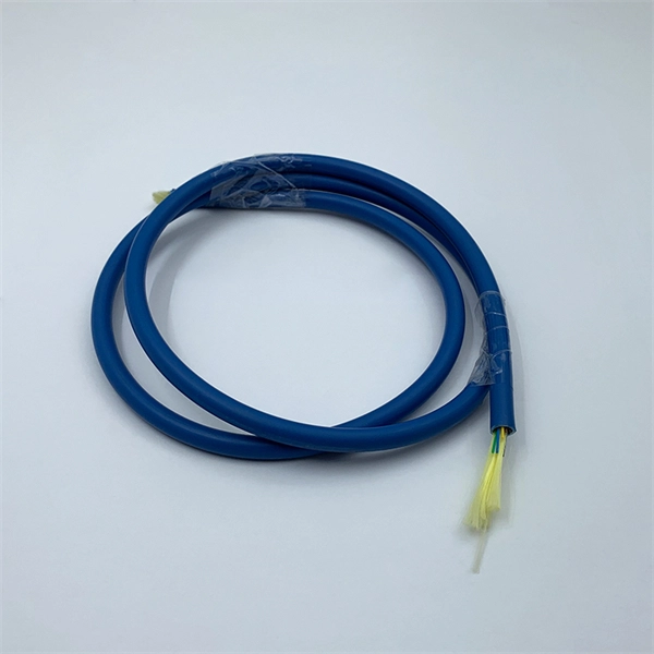
This compact figure 8 fiber optic cable is not only lightweight and flexible but also streamlines the installation process. The integrated steel wire messenger design significantly reduces installation costs and time, negating the need for additi. This compact figure 8 fiber optic cable is not only lightweight and flexible but also streamlines the installation process. The integrated steel wire messenger design significantly reduces installation costs and time, negating the need for additional support structures. Ideal for FTTH (Fiber to the Home) networks, this cable simplifies the roll-out. 1. Versatile Single Mode Core Options: 1. Equipped with G.657A1 and A2 fibers, optimized for bending performance and deployment in challenging pathways. 2. Includes the standard G.652D fiber, ensuring compatibility with a broad range of existing infrastructure. 2. Multimode Fiber Core Variants: 1. Offers OM1, OM2, OM3, and OM4 multimode fibers, cat. Choosing Figure 8 fiber optic cable means investing in a solution that offers: 1. Cost savings on installation and maintenance. 2. Exceptional performance with high tensile strength. 3. Adaptability for single-mode and multimode applications. 4. A design that withstands harsh environmental conditions. Whether you are expanding an existing network o.
[PDF]
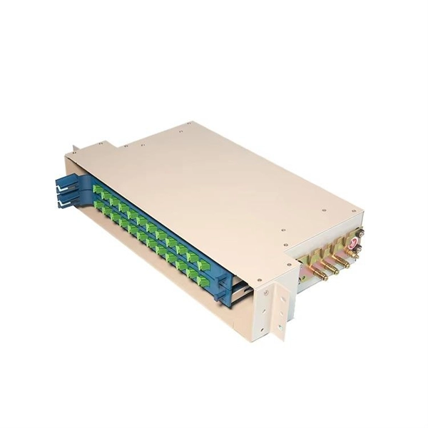
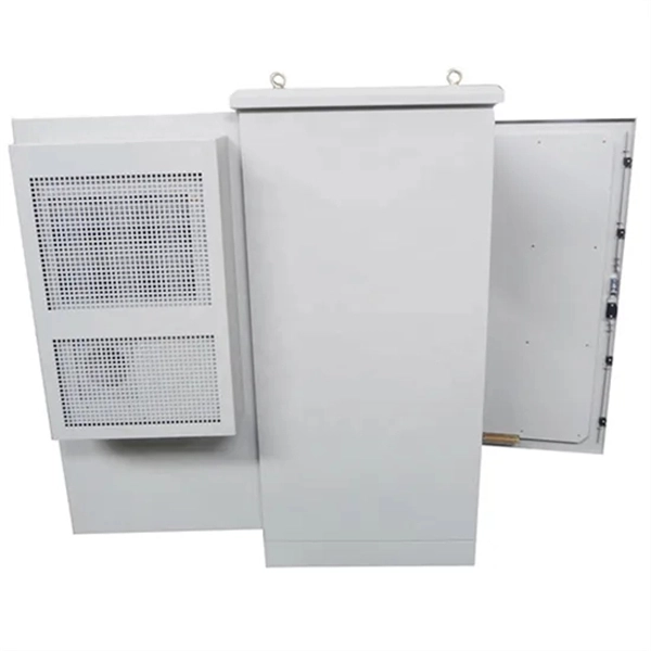
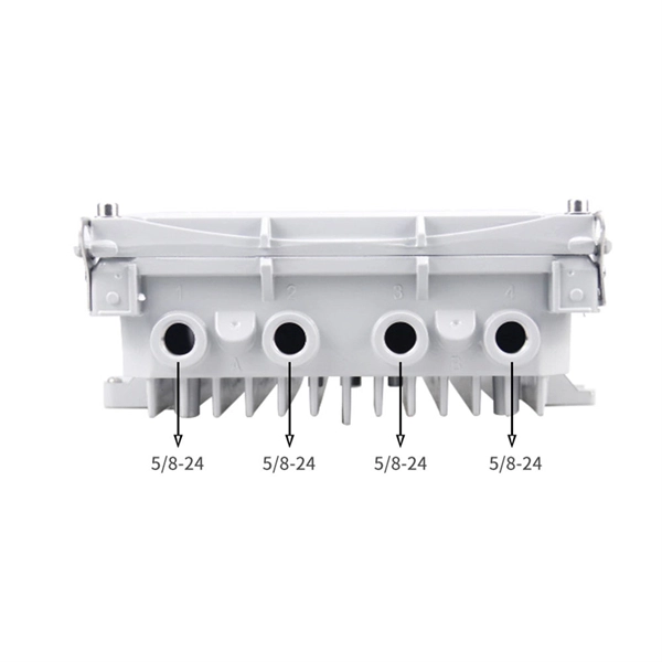
Find reliable optical fiber distribution frame prices for various needs. Shop high-quality, durable ODFs and patch panels for efficient communication networks. Optical Distribution Frame (ODF) is integrated components in any fiber management system to handle termination and cross-connection of cables. Pre-terminated ODFs with cables are pre-installed with connectors and cable for quick and easy installation. It is a device that splices, distributes, and splits optical fibers and provides protection and management of optical fibers. Its box body is made of high quality cold-rolled steel material, and the surface of the product uses smooth electrostatic praying processing. optical fiber distribution frame ODF rack mount 12 24 48 96 144 core port ODF Rack-mount Fiber Optic Distribution Frame is. Streamline your fiber connectivity with our premium Fiber Optic Patch Panels and ODF systems. Designed for reliability and ease of use, our rack-mount and wall-mount solutions provide the perfect environment for splicing, terminating, and managing your critical fiber optic connections.
[PDF]
One important component is the outer jacket of the cable. Outer jackets can be made from a number of materials, and generally speaking, the jacket materials can work with any fiber cable type. That means that choosing the right cable jacket is often. This article explains the differences between LSZH, HDPE, and LDPE cable sheaths, and how to select the right option based on real deployment conditions. What Is a Cable Sheath and Why It Matters 🔍 The cable sheath is the outer protective layer of a fiber optic cable. So the material of the fiber optic cable outer sheath must be able to withstand the sun and rain, and not crack due to ultraviolet radiation. Structurally, a fiber cable comprises the core, cladding, coating, strength member, and outer jacket. The fiber jacket protects against moisture, UV exposure, chemicals, and mechanical abrasion. At the same time, it must have. An optical fiber cable is composed of many strands of coated glass optical fibers. Optical fibers are extremely thin strands of ultra-pure glass designed to transmit light signals from a transmitter to a receiver. These light signals represent encoded electrical signals that include video, audio.
[PDF]
Attenuation is the natural loss of signal power over distance. This is inherent in all fiber types and happens even under ideal conditions. Factors such as wavelength and fiber quality influence attenuation. At shorter wavelengths like 850nm, attenuation is higher, especially in. To be able to judge whether a fiber optic cable plant is good, one does a insertion loss test with a light source and power meter and compares that to an estimate of what is a reasonable loss for that cable plant. The estimate, called a "loss budget" is calculated using typical component losses for. A significant signal loss in the optical fiber can cause unreliable transmission. How can we know the value of losses on the fiber link? Read on, this post will teach you how to calculate the losses in optical fiber and judge the fiber link performance. What is optical fiber loss? Fiber loss can be. At TREND Networks, we are frequently asked how much loss is allowed when conducting testing on fiber optic cabling. So how do you determine acceptable loss? When testing fiber optic cabling, determining acceptable loss is. Understanding fiber loss is vital in maintaining a reliable, efficient network. While some loss is expected, excessive or unexpected loss can lead to poor performance, network. Optical fiber loss is a term for signal loss affecting transmission reliability. So how is the fiber attenuation calculation? 1, ODN full attenuation accounting: According to the worst value.
[PDF]
Stranded fiber optic cable is a loose tube made of high-modulus plastic by adding colored optical fiber and ointment at the same time, and the optical fiber can move in the tube. Different loose tubes are twisted along the central reinforcing core to make the cable core. A TOSLINK optical fiber cable with a clear jacket. These cables are used mainly for digital audio connections between devices. The cable core is added. A steel messenger is a stranded steel cable that acts lashing wire. This document describes further details of messenger strand, lashing wire, and the planning and installation process. Steel messenger strand consists. Fiber optic cables are used to transmit data and audio signals using light. They come in different types, each designed for specific applications and distances. This guide will help you identify the most common types of fiber optic cables and understand how many strands of fiber are typically found. Unlike copper wires, which are limited by lower data transmission speeds, shorter transmission distances, and higher susceptibility to electromagnetic interference, fiber optic cables offer unparalleled performance and can cover much greater distances without bumping up against signal degradation. Fiber optic "cable" refers to the complete assembly of fibers, other internal parts like buffer tubes, ripcords, stiffeners, strength members all included inside an outer protective covering called the jacket.
[PDF]
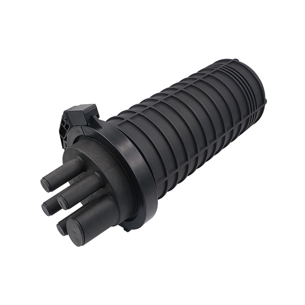
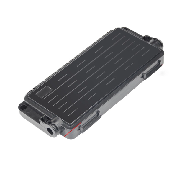
Splice the Pigtail:Fusion-splice incoming fiber to pigtail inside the box. Test:Verify light levels: -27 dBm to -8 dBm (GPON ideal). A fiber termination box is the standard instrument used in fiber optic networks to connect, secure, and protect optical fibers at the terminating point. It functions as a junction between the incoming fiber cable and the outgoing customer-side fiber cable, where one fiber can be spliced, patched. While a cut or damaged fiber optic cable can temporarily take your network down, it is possible to quickly fix the cable with the right tools. This wikiHow article will teach you how to splice a cut fiber optic cable back together with a fiber optic stripper and cutter and a fiber optic crimper. Proper installation and maintenance of FTBs are essential to ensure the reliability and performance of the network infrastructure. After an optical cable arrives at the user's end, it is fixed in the terminal box. These. To establish easy and safe installation put the box where it will be installed and measure the required length of the cable. 5 meter or more, to. Learn how to install a fiber optic termination box step-by-step for FTTH projects. Covers mounting, splicing, routing, labeling, and testing for indoor/outdoor use. Installing a fiber optic termination box is one of those jobs that looks simple on paper, but it's easy to do poorly in the field.
[PDF]
OFC 2020 returns to San Diego Convention Center, San Diego, California, 8-12 March 2020 for another groundbreaking program as the world's largest conference and exhibition for optical communications and networking. SAN DIEGO — Explore the latest in optical communications innovation, data-center connectivity, machine learning/artificial intelligence (AI), applications of optical networks in 5G and cloud computing at The Optical Networking and Communication Conference & Exhibition (OFC), the single-most. This program contains the latest information up to 21 January 2020. Considered the hub of the industry, OFC represents the entire ecosystem—from. OFC 2020 - Optical Networking and Communication Conference & Exhibition, co-sponsored by OSA (Optical Society of America) and the IEEE Photonics Society. The OFC audience spans the entire industry, from scientists and engineers to manufacturers and service providers. It provides the industry's most. *** This is a print representation of what appears in the IEEE Digital Library. Some format issues inherent in the e-media version may also appear in this print version. Chen. The printed show guide for the exhibition contains a list of 181 booth cancellations, which the event organizers indicate was accurate as of March 2. A corner of the OFC 2020 show floor at 2:15 PM PDT on March 10. The exhibit floor at OFC 2020 in San Diego opened today. Reports from sources in.
[PDF]
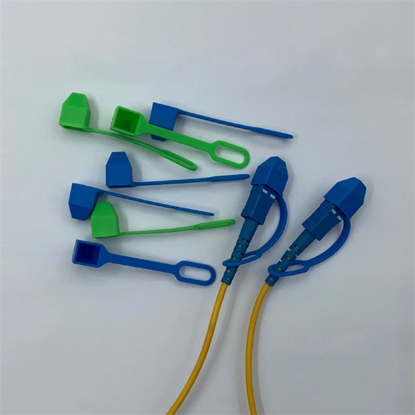
Instead of fusing one fiber at a time, mass fusion splicing can fuse up to all 12 fibers in one ribbon at once. Many of today's cables with high fiber count involve subunits of 12 fibers each that can be quickly ribbonized. Fiber optic joints or terminations are made two ways: 1) splices which create a permanent joint between the two fibers or 2) connectors that mate two fibers to create a temporary joint and/or connect the fiber to a piece of network gear. Either joining method must have three primary characteristics. Fiber optic splicing is the process of seamlessly joining two single Splicing has a lower optical loss and back-reflection than other terminations, making it the ideal choice for maintaining signal integrity and reliability in fiber optic networks. There are numerous use cases for fiber optic splicing. Through splicing, fiber optic technicians can extend the length of the fiber to make it long enough for use in a required cable run. As. To begin, the standard definition of splicing in optical fiber is joining two fiber optic cables together. The other, more common, method of joining fibers is called termination or connectorization. Splicing is most commonly used in the field but has application in cable assembly houses.
[PDF]