Positive busbars, which collect all positive connections. Key Steps: When wiring a pair of 12V busbars, connect the positive terminal of each load to a stud on the positive busbar and their negative terminal to a stud on the negative busbar. 5' above batteries on inside of cockpit combing below decks. Install one new positive bus bar beside the negative one separated by about two inches 3. Positive and negative busbars are physically identical apart from the red/black colours used by some manufacturers to visually differentiate between. A Complete Guide to Battery Terminal Connector Types The store will not work correctly in the case when cookies are disabled. JavaScript seems to be disabled in your browser. For the best experience on our site, be sure to turn on Javascript in your browser. Skip to Content Blog Sign In Create an. This image illustrates a standard car battery with top post terminals and labeled connectors for the positive (+) and negative (–) ends, emphasizing safe and correct installation. A battery terminal connector is a fitting or clamp that attaches to a battery's terminal to connect a cable. In other. Both positive and negative terminals are the soul of the electrical system of the car, allowing the engine to start while keeping other components running. The catch? Mix-up or loose connection can cause electrical failure, drained batteries, and damage to wiring. This blog guides you how the two.
[PDF]
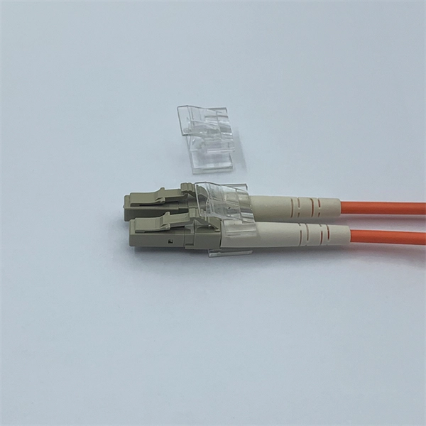
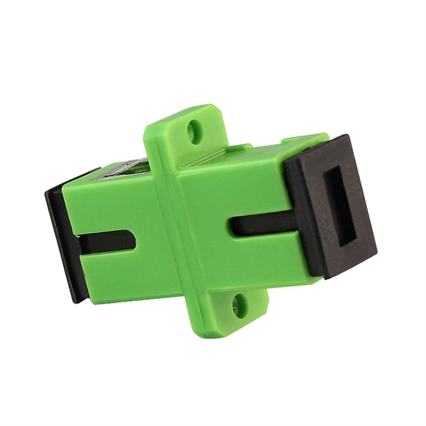
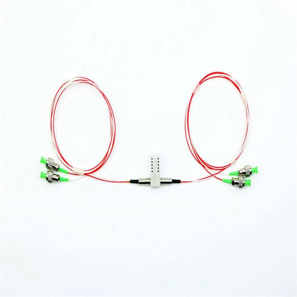
Fiber optic connectors can be categorized according to different standards such as utilization, fiber count, fiber mode, and transmission method. They are also divided into single-mode and multimode types based on their distinct characteristics. The fiber connector types, sometimes referred to as terminations, link fiber optic cables together through terminals, switches, adapters, and patch panels, by bridging the gap between their internal glass fibers that transmit the data down the length of the cable. And based on the connector construction, LC connector also can be divided into LC duplex and simplex connector. a single mode fiber (SMF). And it has a “square shaped” connector body, which is the source of name “square connector”. Due. Fiber optic connectors, according to the different transmission media, can be divided into common silicon-based fiber single-mode and multimode connectors, and other such as plastic as the transmission medium of fiber optic connectors; according to the connector, structure form can be divided into:. A fiber optic connector is a mechanical device used to align and join optical fibers, enabling light to pass through with minimal loss. Simplex vs duplex fiber connectors, single mode vs multimode fiber connectors, what's the difference? This article will explain the above to you.
[PDF]
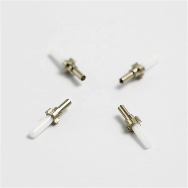
The simplest method: connect two cables pre-connectorized via a coupler (also called an adapter). The coupler aligns the two ferrules of the connectors using a zirconia sleeve. Why connect two fibers? Do you need to extend, repair, or connect two fiber optic cables? There are three methods main ones, each with its advantages and limitations. This article explains when. Optical fiber fast connectors, also known as cold connectors, are becoming increasingly popular due to their ease of use and quick installation. Unlike traditional fiber connectors that require epoxy and polishing, fast connectors use a mechanical splice to join the fibers. Another method is using a mechanical splice which involves aligning and securing the fiber ends with a precision. Fiber optic cables can be connected together using a couple of different methods: 1. This creates a permanent and low-loss connection. Connectors play a crucial role in our daily lives, yet there are some connectors that remain less familiar, such as fiber optic fast connectors. The goal is clean.
[PDF]
There are currently three methods of looking inside a fiber optic connector: (1) Non-destructive X-ray (2) Lossless sonar (3) Destructive cross section These methods help engineers determine the causes and effects of fiber optic connector failures and monitor the connector assembly. There are currently three methods of looking inside a fiber optic connector: (1) Non-destructive X-ray (2) Lossless sonar (3) Destructive cross section These methods help engineers determine the causes and effects of fiber optic connector failures and monitor the connector assembly. Fiber Optic Center offers a unique cross-sectioning service to identify and isolate problems related to fiber optic terminations that would otherwise be invisible. All. There are two major uses for visual inspection of fiber optic connectors. Video microscopes should have ability to record images and some may have ability to analyze connector condition to standards. Look for dirt, contamination, scratches or any other problem. Since connectors are susceptible to damage that is not immediately obvious to the naked eye—the inspection phase is vital. When proceeding with the inspection of connectors, there are two main components to inspect: the connector itself and the ferrule. With the press of a single button, FOCIS Flex auto-focuses, captures and centers the end-face image, applies Pass/Fail rules, displays image and Pass/Fail results, saves results internally and/or wirelessly transfers data to a.
[PDF]
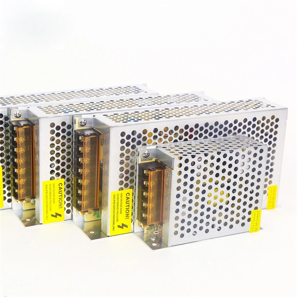
This paper proposes a mathematical model for busbars used within a high current power supply. The obtained thermal model can be used to analyse the thermal behaviour of busbars in steady-state conditions at different values of the electric current, cross-section and length. Improving surface temperature measurement of the power cable and insulated busbar using the heat insulated layer Abstract The surface temperature measurement is susceptible to the surrounding air for the cable or the insulated busbar laid in free air. Therefore, an approach for improving their. The thermal analysis takes into account the heat conduction and convection of a copper busbar system used to supply a test bench with high currents in order to check the electro-thermal behaviour of power circuit breakers during overload and short circuit conditions. This paper proposes a. Current is supplied via bus bars or wire bonding in power supply lines for power electronics devices such as inverters. Because inverters and similar devices operate with PWM carrier frequencies of several kHz, high-frequency current flows in their bus bars. Influences from the skin effect cannot.
[PDF]
Voltage/BIL: 35 kV class, typical BIL 170 kV. Short-circuit: 25–40 kA short-time withstand common; confirm with system fault study. Continuous current: 1250–3150+ A bus and feeder options. Standards: IEC 62271-200; internal arc testing per IEC/TR 61641 if specified. The Insulation levels for Distribution, Class 1 and Class 2 transformers shall be selected from this table for both the high-voltage and low-voltage windings. All test levels are line to ground. The applied test levels are not applicable to wye-connected windings unless they have been specified to. PURPOSE: To provide general construction requirements for representative wood pole structures and assemblies for 34. 5 through 69 kV transmission lines. 2-1. Most distribution voltages are between 4 and 35 kV. In this article, unless otherwise specified, voltages are given as line-to-line voltages; this follows normal industry practice, but it is sometimes a source of confusion. A voltage class is. This article is for manufacturing, testing of non-segregated Bus Bars and Bus Ducts rated 600 V to 35 kV as per international standard ANSI C37. Air insulation with generous. Rated maximum voltage, kV BIL, kV Manufacturing Date: MM/YYYY Rated continuous current, A Rated load interrupting rating, A Momentary current rating, kA asym. Close & latch rating, kA asym. Liquid dielectric volume (gallons) – Liquid-Filled Units Only SF6 Weight, Pressure – SF6.
[PDF]
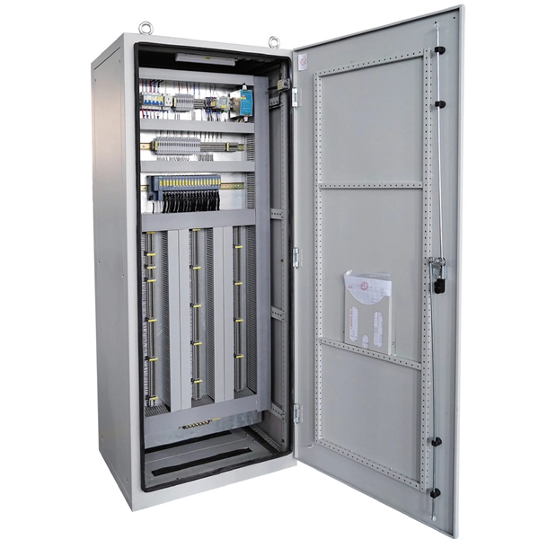
Find competitive prices for Busbar Trunking Systems at Shanghai Qiongkai Industry Co. Connect with reliable manufacturers and suppliers to meet your project needs today!. Buy Busbar Trunking Manufacturers China Direct From Busbar Trunking Manufacturers Factories at Alibaba. Help Global Buyers Source China Easily. Consider factors like conductivity, weight, and corrosion resistance. Use a material guide to select the top choices suited for your applications. Consult with. Finding a balance between quality and cost for your Busbar Trunking Systems is essential. Each product undergoes rigorous testing to ensure durability and efficiency for electrical. Scroll down to check an exclusive list of top China wholesale busbar trunking system suppliers, manufacturers (OEM, ODM & OBM), wholesalers, factory lists, distributors, exporters, importers, etc. Import busbar trunking system from various high-quality China wholesale busbar. Zhejiang Rutong Electric Technology Co. offers an OEM Bus Trunking System designed for efficient power distribution in large buildings and industrial environments.
[PDF]
Join me in this concise video as I demonstrate the meticulous process of connecting stranded wires in a junction box through soldering. Whether you're a DIY enthusiast or a professional electrician, this brief tutorial offers valuable insights into using soldering for. I was changing a switch in my house when I found a number of connections in the electrical box that were soldered rather than secured with a wire nut. The solder joints look very well done, the conductors were twisted together nicely and the solder itself was nicely done. It was not some oxidized. I have found several soldered wires inside junction boxes in my older lake house. I see mostly neutrals this way with the hots going to outlets or switches where they are looped onto the screws. If I am upgrading the junction box to a larger one I just cut the. I don't know why anyone would do this now a days but thats the interesting thing about being an inspector. I inspected a house today that someone is wiring the old school way. The grounds he used wire nuts on. more Join me. Because of different characteristics of dissimilar metals, devices such as pressure terminal or pressure splicing connectors and soldering lugs shall be identified for the material of the conductor and shall be properly installed and used. No wiring systems of any.
[PDF]