This paper proposes a mathematical model for busbars used within a high current power supply. The obtained thermal model can be used to analyse the thermal behaviour of busbars in steady-state conditions at different values of the electric current, cross-section and length. Improving surface temperature measurement of the power cable and insulated busbar using the heat insulated layer Abstract The surface temperature measurement is susceptible to the surrounding air for the cable or the insulated busbar laid in free air. Therefore, an approach for improving their. The thermal analysis takes into account the heat conduction and convection of a copper busbar system used to supply a test bench with high currents in order to check the electro-thermal behaviour of power circuit breakers during overload and short circuit conditions. This paper proposes a. Current is supplied via bus bars or wire bonding in power supply lines for power electronics devices such as inverters. Because inverters and similar devices operate with PWM carrier frequencies of several kHz, high-frequency current flows in their bus bars. Influences from the skin effect cannot.
[PDF]
Temperature measurement on a 10kV fully insulated busbar is studied in , also for the joint conductor, for which the temperature rise is lower because of the heat dissipation. The temperature can be decreased by using slots in the contact area, as presented in. Copper busbar technology is widely used with the aim to achieve electrical connections with power distribution systems because of their flexibility and compactness. The thermal analysis takes into account the heat conduction and convection of a copper busbar system used to supply a test bench with. IEC 61439 is a standard developed by the International Electrotechnical Commission (IEC) that covers design verification for low-voltage electrical products and assemblies. This standard defines the design verification, test requirements, and thermal performance of the assemblies. The IEC 61439. If the busbars are coming from a piece of switchgear then the temperature rise for those busbars would be governed by the standard you mention. Do you have any info on the temp rise for the transformer? “Do not worry about your problems with mathematics, I assure you mine are far greater. It includes two parts: the power conditioning system (PCS) converter, which connects the system to the grid and is the key component to provide grid support services, and the.
[PDF]
Because bus bars are conductors that carry large electrical currents to manufacturing equipment, they are often covered with bus ducts, making visual inspection difficult. In addition, bus ducts (bus ba.
[PDF]
Fiberglass trays are the least effective at dealing with heat. Fiberglass cable tray loses 10% of its rated strength at temperatures as low as 100°F. Eaton's B-Line series fiberglass cable tray systems provide an economical support system with superior strength at room temperatures and dependable load bearing capabilities at continuously elevated temperatures. While fiberglass cable tray systems utilize a heat-cured resin that doesn't melt at. Choosing fiberglass cable trays for elevated-temperature environments requires moving beyond supplier claims. Your assurance as an engineer should be based on evidence, specifically the Air Thermal Aging Test Report. You don't need to be a materials expert. You need to know how to evaluate three. Our trays are manufactured from Fiberglass Reinforced Plastic (FRP) using high-grade resins to ensure outstanding corrosion resistance, mechanical strength, and electrical insulation. FRP Cable Trays are a superior alternative to conventional steel or aluminum trays, particularly in aggressive. Fiberglass Ultra-Sleeve High-Temperature Sleeving is a protective sleeve that is ideal for those areas where your cable runs through a particularly harsh environment of flash heat or flame, chemical or mechanical abuse.
[PDF]
(1) The admissible load of a complete system depends on the system topography and the application parameters. Factors of influence are ambient temperature, air circulation, busbar load, distribution of busbar loa.
[PDF]
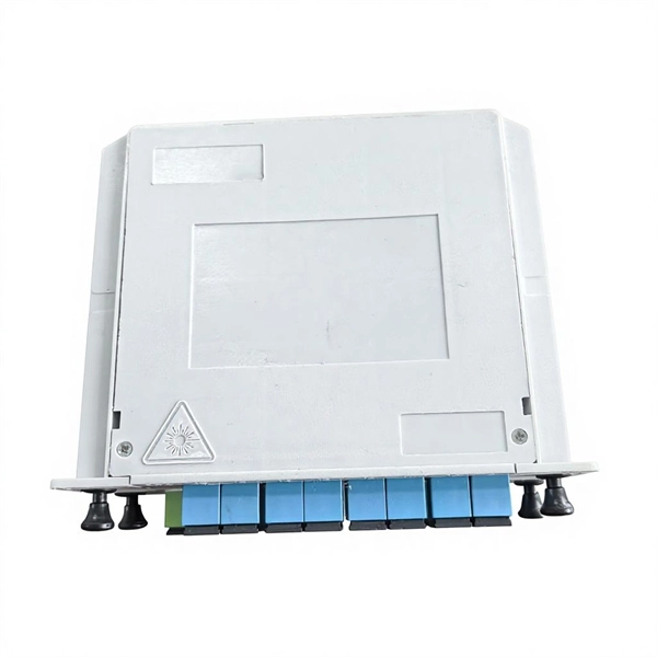
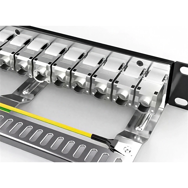
Busways, or bus ducts, are long busbars with protective covers. Rather than branching from the main supply at one location, they allow new circuits to branch off anywhere along the busway.OverviewIn , a busbar (also bus bar) is a metallic strip or bar, typically housed inside,, and for local high current power distribution, transmission, or switching s. The busbar's material composition and cross-sectional size determine the maximum current it can safely carry. Busbars can have a cross-sectional area of as little as 10 square millimetres (0.016 sq in), but. • – Data transfer channel connecting parts of a computer• – Low resistance electrical conductor for high current transmission and distribution• – Modular approach t.
[PDF]
🔧 Step 1: Busbar surface preparation & cleaning 🔥 Step 2: Welder setup ( [Specify type: TIG/Resistance/Laser]) ⚡ Step 3: Demonstration of welding technique. more. Seamless bus pipe is an extruded tubular product used to convey electricity. It is manufactured to a “nominal,” not actual, inside diameter. The wall thickness is described by a "schedule. " The schedules are determined by the American Standards Association. Sometimes we tig alot of the prefab and wire weld our field welds. Some weld joints need prheat others dont. We run GMAW-P on some of the thicker parts in. Weld your busbars with ultrasonics to permanently benefit from strong connections without contact resistance — even with different metals like aluminum and copper. Discover the benefits of our innovative welding technology for more output, control, and efficiency in your production! to 12 s per. The connection of copper busbars in power stations mainly involves two methods: bolt fastening and welding. Copper has excellent electrical conductivity, thermal conductivity, heat resistance, and formability. Industrial pure copper is not less than 99. Copper Welding Characteristics The. Diffusion welding creates a permanent bond between metal surfaces by applying pressure and high temperatures for an extended period of time. Diffusion welding relies on atomic diffusion between pressed surfaces, forming a robust, long-lasting bond. Diffusion welding can handle dissimilar material.
[PDF]
Ever wondered how busbars, the unsung heroes of electrical distribution, are processed and installed? This article delves into the intricate steps of busbar selection, preparation, and installation, ensuring efficient and safe power distribution. You'll discover the essential tools and techniques. Discover the four types of busbar processing machines, from manual to fully automated solutions. Busbar processing machines play a pivotal role in the electrical industry, particularly in the fabrication and. Cut, bend, and punch smoothly to boost productivity for manufacturers and contractors in electrical distribution. Deliver high-precision, efficient metal bending with intelligent automation solutions for your electrical engineering projects! Enhance your busbar manufacturing with precision and. Established in 2005, LT Machinery has over 20 years of experience in the research and manufacturing of busbar processing technology. LT Machinery provides a complete set of solutions for punching, cutting. Cut, Punch and Bend all sizes of copper or aluminum busbar. Field service tools through to in-plant production systems. Capacity: 3/8" x 4-1/2" (10 x 120 mm) A complete cut, punch and bend system Single hydraulic cylinder and work area. Easily change between cutting, punching, and bending.
[PDF]
Operating at 10kV with a normal-pressure sealed structure, it uses air as the insulating medium (eliminating reliance on SF₆ gas) and features modular cabinet designs that can be flexibly combined. The AHVAC10KV10MABT is a ac-dc high voltage power supply designed for ac-dc benchtop high voltage power supplies. It converts 90 to 230V input into a high voltage output up to 10kV, with a maximum output current of 10mA. The module is designed for stable AC-DC high voltage conversion, offering. In electric power distribution, a busbar (also bus bar) is a metallic strip or bar, typically housed inside switchgear, panel boards, and busway enclosures for local high current power distribution, transmission, or switching substations. They are key components in electrical systems that can efficiently collect and distribute electricity. In this blog, I will introduce busbars in detail. Its primary role is to carry large current loads and connect multiple circuits together. When the required voltage is achieved, then rotate the potentiometer lock clockwise to High efficiency AHVAC10KV10MABT, is designed for achieving AC-DC conversion from AC voltage. The 10kV (Flexible Combination of Multiple Cabinet Types) Normal Pressure Sealed Air-Insulated Switchgear / Ring Main Unit is a versatile medium-voltage power distribution system designed to adapt to diverse operational needs.
[PDF]
Its primary role is to carry large current loads and connect multiple circuits together. Think of a bus bar as the main highway for electrical current—allowing it to flow between components with minimal resistance and voltage drop. In electric power distribution, a busbar (also bus bar) is a metallic strip or bar, typically housed inside switchgear, panel boards, and busway enclosures for local high current power distribution, transmission, or switching substations. Think. The electrical panel, often called the breaker box, functions as the central distribution point for all electricity entering a home. While circuit breakers are the visible safety components, the internal system that routes and distributes the power is built around the bus bar. It acts as a central hub, connecting multiple circuits and ensuring current flows efficiently. A busbar's main function is to conduct and distribute large electrical currents from one source to multiple circuits within an enclosure, acting as a central, high-capacity connection point. My insights show that understanding the practical function is key. As I've seen in the field, the textbook.
[PDF]
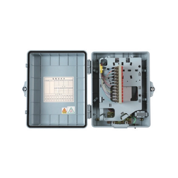
This is not a normal operating temperature, and excessive heat is a serious indicator of an internal fault that could lead to component damage or an electrical fire. Recognizing this heat as a sign of trouble requires immediate attention to prevent potential hazards. Understanding acceptable circuit breaker operating temperatures will help avoid unnecessary replacements and returns. A circuit breaker that is warm to the touch, or too hot to touch, is normally within acceptable operating temperatures. Therefore, it is important to obtain the temperature reading. Every circuit breaker generates heat during normal operation. When electrical current flows through the internal components—contacts, bimetal strips, and terminals—resistance creates thermal energy. This enclosure houses the circuit breakers designed to interrupt current flow when a fault or overload occurs, protecting the entire wiring system. A breaker box is. While a slight warmth can be normal during heavy usage, excessive heat may indicate a serious electrical problem that shouldn't be ignored. In this post, we'll explore: What's Normal for a Circuit Breaker? Circuit breakers are designed to carry electricity safely through your home's circuits. What emerges is a crystal-clear thermal portrait of the distribution box's interior. Like a doctor reading an X-ray, an experienced engineer.
[PDF]
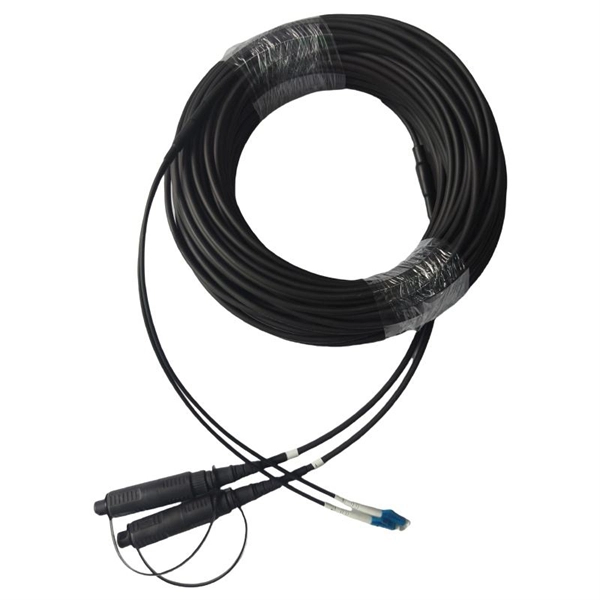
The fundamental principle behind fiber optic temperature sensors is the use of light to measure temperature. These sensors typically employ a phenomenon known as the Raman Effect, where light scattered by molecules in a medium varies depending on the medium's temperature., thermocouples, RTDs), fiber optic sensors offer significant advantages such as immunity to electromagnetic interference. This article explores the different types of Fiber Optic Sensors, their working principles, and various applications. We'll delve into Intrinsic, Extrinsic, and Hybrid fiber optic sensors, explaining how they function. A sensor is a device that measures a physical quantity and converts it into a. Fiber optic sensors represent a cutting-edge technology used in a variety of industries to detect and measure changes in physical parameters such as temperature, pressure, vibration, and strain. These sensors harness the principles of light transmission through optical fibers to monitor conditions. Three sensors presented make use of non-contact vibration measurement method with plastic fiber using distinct designs, improvement of the sensor response and advantages of one sensor over the other for diverse applications. Rayleigh scattering-based phase optical time domain reflectometry (OTDR) for vibration and.
[PDF]
Use this Raman amplifiers buying guide to compare major types, define selection criteria, and find suppliers: Professional purchasing of high-value photonics products is a substantial responsibility, where a structured decision-making process is essential. RP Photonics offers a. Our Raman amplifiers leverage internally developed, state-of-the-art 14xx pump lasers, internally developed intelligent algorithms for autonomous gain control, and robust safety features to deliver network-ready solutions. The first-order Raman amplifier uses 14xxnm laser as the Raman pump to amplify C-band or C+L band signals, effectively compensating for signal. PacketLight's PL-1000R is designed for distributed Raman amplification applications, cost-effectively extending the optical link power budget and significantly improving OSNR. The PL-1000R enables long distance DWDM solutions and facilitates the transport of 100G/200G/400G and 800G wavelengths over. Nuphoton Technologies, Inc. is a pioneer in fiber lasers and fiber amplifiers with applications covering industrial, defense, aerospace, biomedical, telecommunications and research areas.
[PDF]
The optimal Electrical Panel Temperature Range lies between 40ºC (105ºF) and 50ºC (122ºF). As the internal temperature of the components increase, their lifespan will decrease. Discover smart ways to manage heat in electrical enclosures, from heat load to cooling systems, for safe, reliable equipment performance. If it gets too hot, parts can stop working or even catch fire. If it gets too. bility of the electronic components by 50%. As technology advances, electronics get smaller, leading to more electronic comp nents inside a single electrical enclosure. These tightly packed components help conserve space and allow for more eficient automation but leave very little room f r heat. Electrical enclosures serve to protect electrical devices from adverse environmental influences, such as dirt, other particulates, moisture, or chemicals that could damage components. Plus, by housing electrical devices inside a secure enclosure or box, personnel are protected from electrical. Temperature can dramatically impact your electrical components. Your electrical devices might be rated for operation up to 60°C (140°F), but proper cabinet ventilation is vital to prevent equipment failures. You must incorporate thermal control in the initial designs of electrical enclosures to save yourself the trouble due to temperature related.
[PDF]
According to the different operating temperature range of FBG produced by DCYS, it can be divided into: Standard Fiber Bragg Gratings (operating temperature range from -40°C to above 100°C). High-temperature resistant Fiber Bragg Gratings (operating. Fiber Bragg grating (FBG) sensors have emerged as advanced tools for monitoring a wide range of physical parameters in various fields, including structural health, aerospace, biochemical, and environmental applications. Low-temperature. Abstract—Various types of high temperature fibre Bragg gratings (FBGs) for sensing applications, are briefly reviewed, discussing their various figures of merit and performance. References are provided to currently available commercial grade high temperature FBG sensors. Keywords—Fibre Bragg. They can reach over 500°C at significant depths in addition to the extreme pressures. Due to their small size, capacity to be multiplexed into high density distributed. FBG temperature sensors are investigated for cryogenic, ambient, high-temperature and ultrahigh-temperature environments. Interrogation techniques encompasses optical interferometry, optical edge filtering, time division multiplexing, optical spectrum analysis (OSA) and wavelength division.
[PDF]