Abstract: Detecting partial discharges in cable joints is critical for timely defect identification and reliable transmission system operation. The electric field distribution of the optical fiber-implanted cable joint was simulated, followed by electrical performance tests, demonstrating that optical fiber implantation had a negligible effect on the electrical properties of the cable joint. A platform utilizing Mach–Zehnder–Sagnac. The results show that the average sensitivity of the sensor in the 10 kHz–80 kHz range is 71. 0 dB higher than that of the piezoelectric transducer, with a maximum signal-to-noise ratio of 65. To improve the long-term reliability and sensitivity of the sensing system, a novel method for cable joint monitoring based on implanting optical fibers. However, there is an industry gap in the literature about the highly sensitive fiber optic-based PD solution based on the acoustic emission principle. This paper aims to fill such an industry gap. In this paper, the fiber optic-based PD sensing (OptiFender) technology is applied to monitor the PD.
[PDF]

Discover the key differences between optical fiber cables and copper cables. OPTRAL analyzes the advantages and disadvantages to enhance connectivity. Optical and copper interconnection technologies represent two distinct approaches to data transmission, each with its own advantages and limitations. While fiber optics dominate in performance, copper retains its technical and economic justification. But how do you decide which one is best suited for your needs? This article delves into the technical comparison between copper and fiber optic cables. When it comes to modern data transmission, Fiber Optic cables and Copper Cables play pivotal roles in ensuring seamless connectivity. What Are Fiber Optic Cables? Fiber Optic cables function by transmitting data in the form of light pulses through optically pure glass fibers. These fibers are. “Fiber offers multiple technical advantages, including exceptional bandwidth, low attenuation and distortion over long distances, reduced bulk, as well as isolation from electromagnetic interference (EMI) and electrostatic discharge (ESD). ” Let's explore the characteristics, advantages, and. The two core material technologies used in almost all cables are fiber optic, and copper wiring. Whether you're looking at an HDMI cable, a USB cable, Ethernet patch cable, or any other kind of network of data transmission cabling, they are all built using copper or fiber optic internal wiring.
[PDF]
This Technical Brochure describes the induction phenomena (inductive, capacitive and conductive) that can lead to presence of voltage and currents on disconnected cable systems. The optical fiber composite overhead ground wire (OPGW) has been widely used in power transmission lines. Methods of calculation to evaluate those values and touch voltages are detailed and analysed, associated with various. working on cables u al, photocopying, recording or otherwise, without the prior written or use by members of the Energy Networks Association to take account of the conditions which apply to them. Advice should. Literature review: An in-depth literature review covering the modelling and calculations of the conditions relating to faults caused by interactions between fibre optic cables and power cores in submarine cables. Examples of electrically conductive installations where induced voltage may occur could be: • Overhead lines or cables out of opera- tion •.
[PDF]
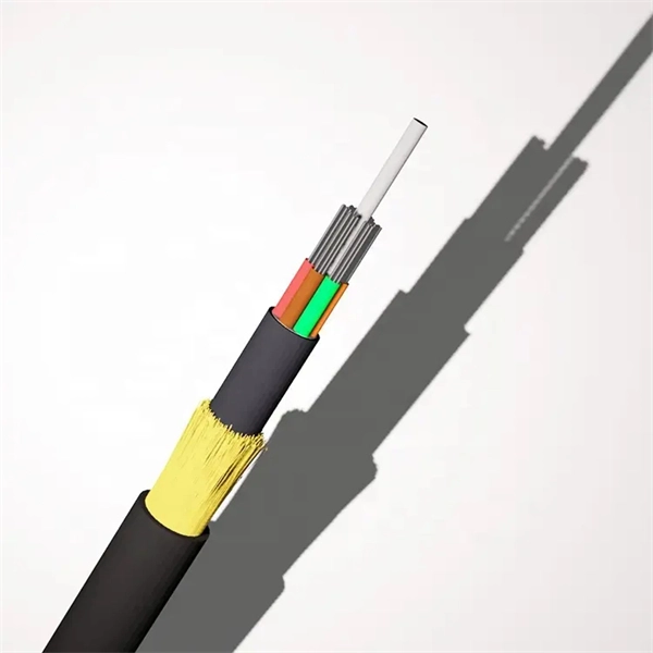
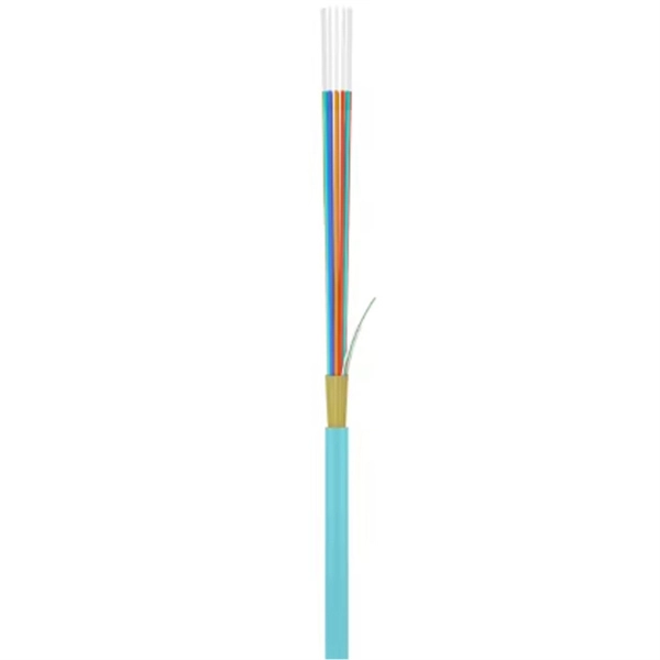
Fiber optic "cable" refers to the complete assembly of fibers, other internal parts like buffer tubes, ripcords, stiffeners, strength members all included inside an outer protective covering called the jacket. Cable provides protection for the optical fiber or fibers within it appropriate for the environment in which it is installed. You will also learn how different aspects of the product can affect budget and design. ■ The Five Key Parts of a Fiber Optic Cable A fiber optic cable. A fiber optic cable consists of five basic components: the core, the cladding, the coating, the strengthening fibers, and the cable jacket. When searching for a fiber optic cable, we need to pay attention not only to the connectors, such as SC to ST fiber cable, LC to SC fiber patch cable, or SC to. A TOSLINK optical fiber cable with a clear jacket. These cables are used mainly for digital audio connections between devices. This advanced cabling solution allows fast, secure data transfer and telecom over long distances. Understanding the components within a fiber optic cable enables. While fiber optic cable itself is cheaper than an equivalent length of copper cable, fiber optic cable connectors and the equipment needed to install them have typically been more expensive than their copper counterparts.
[PDF]
While fiber itself is constructed of thin, fragile filaments of glass, fiber cables that are laid outdoors are built for durability. Fiber optic internet represents a significant leap forward in broadband technology, offering speeds and reliability far exceeding traditional cable or DSL connections. Unlike older technologies that rely on electrical signals transmitted through copper wires, fiber optics use thin strands of glass. Unlike traditional copper wires that carry electrical signals, fiber optics use thin strands of glass or plastic to transmit data as pulses of light. This fundamental difference is the key to its superior speed, bandwidth, and reliability. The light signals travel at near the speed of light. Installing fiber optic cables underground involves far more than digging trenches and placing cables. It forms a critical backbone for modern communication networks across both urban and rural environments. Unlike traditional copper systems, fiber optic cables require specialized handling techniques and precise installation methods to. In our digital age, high-speed internet and reliable communication networks are powered by fiber optic cables, which transmit data as light signals at incredible speeds. However, the performance of fiber optic technology depends heavily on proper fiber optic cable installation.
[PDF]
List of Top Verified Cabling and Fibre Optics Companies in Jordan, Near Me. Last updated May 2026. TechLine, a large-scale factory founded in Jordan in 2016, is situated in the Al Qastal industrial area of Amman. It holds ISO 9001:2008 certification, marking a milestone as the inaugural establishment of its kind in the Middle East. As part of a private investment consortium alongside Amwaj. Complete FTTx passive equipment - from fiber cables to distribution systems - plus reliable energy infrastructure, engineered with precision and trusted quality. Techline offers a. IT infrastructure and security solutions with quality commitment. Leading IT solutions in software, hardware, and networking. Complete networking solutions and services. Telephone: (5606205/3) Main Objectives: Manufacturing electric, power cables, and telephone wires. Let Optical Fiber Cables sellers contact you. No Time to Search? Post Your Buy Requirement to Suppliers Worldwide. Best prices, bulk discounts, trusted deals at go4WorldBusiness. Under the valuable guidance of Ziad Al-Omoush International Company for wires and cables manufacturing is now one of a fast growing company in the Hashemite Kingdom of Jordan with brand image of JOCAB. JOCAB manufactures a wide range of quality cables of high performance conforming to INTERNATIONAL.
[PDF]
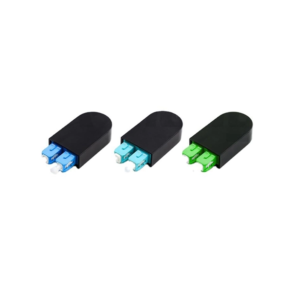
The other side of the pigtail is open and is connected to a fiber optic cable. This creates a stable and reliable connection between network equipment. They are the bridge between fiber optic cables in the field and the equipment or patch panels that manage them. By combining factory-installed connectors with spliced bare fiber, pigtails ensure that network installers can create fast, reliable, and cost-effective terminations. DINTEK supplies this equipment, but the pigtails can also be. In the intricate ecosystem of fiber optic networks, two components play a critical role in ensuring seamless connectivity: patch cords and pigtails. A fiber optic pigtail is a type of fiber optic cable with only one end that has a factory-terminated connector and the other end exposed as bare fiber. When compared to field-installed rapid. Today, I'll show you how to pick the right patch cord or pigtail — step by step. You plug it into a switch, router, or patch panel. It's ready to use out of the box. A pigtail is for splicing.
[PDF]
A shortage of fiber-optic cable equipment is blamed on AI data center demands as well as US protectionism. Warnings about a US fiber crunch that could slow down broadband deployment have intensified since the summer. Very recently, Mitch Landrieu, senior advisor to president and White House infrastructure coordinator made a statement that says, “Just like president Franklin Delano Roosevelt's Rural Electrification Act made a historic investment in rural areas bringing electricity to nearly every home in. According to 2022 data from the United States International Trade Commission, U. manufacturing capacity met only about 53% of the country's demand for optical fiber, the core component of fiber optic cable. currently relies heavily on imports to meet the increasing demand. That's a problem, considering fiber optics are the backbone of modern communications, powering everything from global internet. From a splicer's standpoint, ribbon cable is “much more user friendly and much more organized” because multiple fibers are bonded together. In August, Incab America, a Texan maker of fiber-optic cable, notified customers. However, a significant paradox exists: despite its immense benefits, fiber optic infrastructure is not universally available. This article aims to dissect the multifaceted reasons behind this uneven distribution, providing a comprehensive overview of the challenges and potential solutions for.
[PDF]
Fiber optic cables can be run anywhere from 2 kilometers to over 100 kilometers without signal regeneration, depending on the cable type and application. Fiber optic cable transmission distance is determined by two primary physical factors that affect signal quality as light travels through the fiber medium. The greater the distance, the greater. In this blog, I will discuss the fiber optic cable distance, the effect factors, how to choose the right fiber optic cables, and how to compare the transmission distances of single-mode and multimode fiber optic cables. Single-mode fiber (SMF) supports distances up to 40-100+ kilometers for standard applications, while multimode fiber (MMF) is typically limited. Fiber optic cables are the backbone of modern communications, enabling high-speed data transfer over vast distances. Unlike traditional copper cables, fiber optic cables use light to transmit data, resulting in faster speeds and greater bandwidth capabilities. Chromatic dispersion This is a key factor affecting single mode fiber distance. While this technology offers higher speeds and longer distances than traditional copper wiring, physical limitations impose distance constraints. Light pulses degrade as they travel over long spans, primarily.
[PDF]
Use this worksheet to input values for all variables that will impact your system's performance. After entering your values, please ensure you click the 'Calculate Link Loss' button at the bottom of the page to generate your total link loss. Add connectors, splices, bends, and safety margin easily. See results instantly above the form, then adjust values. Choose a mode, then enter values and optional losses. All calculations use base-10 logarithms. mW must be greater than zero. Used only in measured attenuation mode. Length is needed. The power budget refers to the amount of fiber optic cable plant loss that a datalink (transmitter to receiver) can tolerate in order to operate properly. Sometimes the power budget has both a minimum and maximum value, which means it needs at least a minimum value of loss so that it does not. To detect whether the link runs properly, the following calculation should be performed. It is often the case to calculate the maximum signal loss across a given fiber link during optical cable installation. First, you should be aware of the fiber loss formula: The Total Link Loss = Cable. Therefore, it is very important to calculate the fiber loss and take appropriate steps. In order to get the most reliable results, an Optical Time Domain Reflectometer (OTDR) trace of the actual fiber connection should be completed. This will provide you with the real.
[PDF]
Q: How far can multimode fiber go? A: The transmission distance of multimode fiber depends on the fiber type and data rate. OM3 and OM4 multimode fibers typically support up to 300m and 400m, respectively, for 10G Ethernet. At lower data rates, such as 1G Ethernet, multimode fiber. Multimode fiber optic cables are designed to carry multiple light modes simultaneously, each taking a different path or mode through the fiber. This characteristic makes MMF ideal for high-bandwidth applications over relatively short distances. Common applications include Local Area Networks. Fiber optic cable transmission distance is determined by two primary physical factors that affect signal quality as light travels through the fiber medium. The greater the distance, the greater. A: Single mode fiber can typically transmit up to 160 km, and with dispersion compensation, it can exceed 200 km. For most enterprise or data center applications using multimode fiber, the practical limit sits between 300 m and 550 m. However, the dispersion-compensating fibers can support more than 200 kilometers. How. For instance, without amplifiers, single-mode fiber can reach 50-60 miles and can support data rates of 1 Gbps or 10 Gbps. With amplifiers, such as Erbium-doped fiber amplifiers (EDFAs), the distance can be extended to 600 miles or more, and even further with additional amplifiers for long-haul.
[PDF]
Fiber optic cables are also more secure, as they are harder to tap or hack. Fiber and copper cable repair both require trained splicers, but the tools, techniques, and failure modes are completely different. Sending a fiber splicer to repair a copper cable - or vice versa - wastes time and risks making the damage worse. Here is what you need to know before you call for. Well-made fiber optic cables are very tough, making them great choices for homeowners who would like to limit weather-related internet outages as much as possible. The comparatively high durability of fiber optic cables comes from a series of factors, including: The quality of the glass cables, of. Copper and fiber optic cables each offer distinct advantages and disadvantages that can impact performance, cost, and long-term efficiency. But how do you decide which one is best suited for your needs? This article delves into the technical comparison between copper and fiber optic cables. Fiber optic cables are typically damaged in one of two ways: A premade fiber optic cable suffers connector damage when too much pull-force is applied during installation. This can occur on long cable runs through tight conduit or duct, and also if the cable becomes caught or snagged.
[PDF]
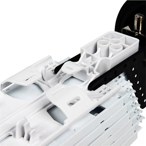
Microducts are pipes used for the installation of fiber optic cables, can be produced in different colors and have high crush resistance. Available Universal Routing Kits 24F or 36F enable quick separation of fibers into 2 x 12 or 3 x 12 fiber sets with a furcation tube that protects the fibers from sharp edges in closures and cassettes. These universal routing kits provide the ultimate solution for those users who want to route. The kink-resistant buffer tube contains multiple 12-fiber sets of color-coded fibers. Each set within the buffer tube is grouped using dual color-coded binder threads. The dry-blocked core is made up of SZ-stranded buffer tubes around a central strength member. The low-friction, high-strength. Loose tube cables to install in microducts (Blowing). Available in high density of fibers. Can be directly terminated. Loose tube cables for indoor and outdoor. Loose tube cables with flexible tubes for indoor. MLT Microduct optical fiber cables are robust solutions for micro duct outside plant installations. They have stranded micro loose tubes and water blocking gel, they ensure durability and reliability. The addition of a thermoplastic dual jacket in certain models enhances resilience and ease of. Prysmian's microduct cables offer a step forward in cable miniaturization by boasting world record fibre densities and cable diameters. EasyFiber® Microduct, have a thin outer jacket for fast and easy installation.
[PDF]
Proper fiber optic termination is a crucial process for ensuring the reliability, performance, and long-term durability of any fiber optic network. The process of fiber optic cable termination is the essential act of connecting fiber optic cables to devices, patch panels, or other. Fiber optic joints or terminations - where cables are terminated - are made two ways: 1) connectors that mate two fibers to create a temporary joint and/or connect the fiber to a piece of network gear (left) or 2) splices which create a permanent joint between the two fibers (right). Thus, you will put the cable across the points, stretch it to determine length, cut it accordingly, and place the connector on each end. After that, the patch panel attaches to it. Each cable has a connector attached. A. Once fiber optic cables have been successfully placed, we can focus on managing the ends of the fibers. This process depends on the project's needs and identifying a solution that aligns with the current situation. We can make suggestions that typically benefit the current circumstances and result. Where copper twisted pairs tend to terminate with an RJ45 plug, fiber optic connectors come in all sorts of shapes and sizes, with all manner of different use cases in mind. An optical fiber connector is used to join optical fibers where a connect/disconnect capability is required.
[PDF]
A practical, engineering-focused guide to planning and installing underground fiber optic cables with the right cable structure, trench design and protection level for long-life, low-risk networks. Match trench method with the correct underground fiber structure (GYTS . Installing fiber underground is one of the most durable ways to protect a network's backbone — when it's done right. Direct-burial fiber cable eliminates the need for continuous conduit runs and can be faster and more cost-effective on long, open runs. But because the cable sits in soil exposed to. 1. 01 This procedure provides general information for the installation of Prysmian fiber optic cables in direct buried applications. The methods described are intended for guideline use only, as it is impossible to cover all the various conditions that may arise during an installation. Individual. ion) and “ Installed” (after installation). The following formulas may be used to determine general guidelines for installing Corning Optical Communications fiber optic cable; however, refer to the cable specifi simply double the minimum working bend radius. Split cable guides and split 40-in. Fiber optic cable transmits data as pulses of light through thin strands of glass, offering superior bandwidth and distance capabilities compared to traditional copper wiring.
[PDF]