In this tutorial, we will learn how to use the DHT11 sensor module with the Micro: bit V2 board. This sensor can measure temperature and humidity; we'll display these measurements on an LCD screen. Also, I have used the Microsoft MakeCode platform to write our code. Welcome to the class on making a temperature and humidity detection device! This project uses a micro:bit board, OLED display, and temperature-humidity sensor connected via the IIC interface of the Petal Base Expansion Board to achieve real-time detection and display of environmental temperature. In this tutorial, we will learn how to use the DHT11 sensor module with the Micro: bit V2 board. MakeCode is great because it. Imagine monitoring real-time temperature, humidity levels, atmospheric pressure, rainfall detection, air quality index (AQI), and more—right from your local network. With the power of the Arduino UNO R4 WiFi, you can create a dynamic weather dashboard web page that displays all your environmental. This project is a smart weather station built using the ESP8266 microcontroller integrated with multiple environmental sensors — BMP180 for pressure and altitude, DHT11 for temperature and humidity, and MQ135 for air quality monitoring. It continuously collects real-time weather data and air. This tutorial is all about Humidity & Temperature Monitoring with DHT11 & STM32 Microcontroller. There is a dht module that comes with the MicroPython firmware by default.
[PDF]
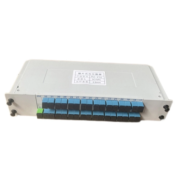
This paper aims to study the design, simulation, and optimization of low-loss Y-branch passive optical splitters up to 64 output ports for telecommunication applications. For a waveguide channel profile, the standard material silica-on-silicon is used. Two important technologies for optical layer monitoring are Optical Performance Monitoring (OPM) and Optical Power Detection (OPD). Although they aim to maintain network health, they differ significantly in scope, technique, and deployment. This article delves into these differences, equipping. Optical Performance Monitoring (OPM) is considered a necessity over an optical network to enable sensibility of traffic line status and attain outstanding Quality-of-Service (QoS). The Y-splitters are designed and simulated at. Passive optical networks (PONs) are the network architecture of choice for residential fiber deployments. A PON is designed specifically to be cost-effective for delivering high data-rates to large customer populations. signals and various components of OPM functionalities are indispensable robust network operation and plays a key role flexibility and improve overall. Optical performance monitoring (OPM) is used for managing high capacity dense wavelength-division multiplexing (DWDM) optical transmission and switching systems in Next Generation Networks (NGN). OPM involves assessing the quality of data channel by measuring its optical characteristics without.
[PDF]
By combining compact laser sources with sub-1 ml volume and ultrastable optical cavities, this work enables extremely compact and robust ultrastable laser systems with applications in low phase noise microwave generation, sensing, and satellite ranging. The Laser Light Screen System faces critical technical challenges in high-speed, long-range target detection: when a target passes through the light screen, weak light flux variations lead to significantly degraded signal-to-noise ratios (SNRs). Traditional signal processing algorithms fail to. Ultra-low-noise microwave signals play a driving role in the development of modern scientific technologies such as radar, communication, and sensing. On-chip photonic integration provides an attractive approach for the implementation of ultra-low-noise microwave signal sources with attractive added. We demonstrate thermal-noise-limited direct locking of a semiconductor distributed feedback (DFB) laser to a sub-1 mL volume, ultrastable optical cavity, enabling extremely compact and simple ultrastable laser systems. Using the optoelectronic laser locking method, we realize over 140 dB. Here we address these shortcomings with a hybrid optoelectronic approach that combines simplified optical frequency division with direct digital synthesis to produce tunable low-phase-noise microwaves across the entire X-band (8–12 GHz). Traditional signal processing algorithms.
[PDF]

On the US market, a 5. 26 mm 2 (10 AWG) ground wire must be used, and in all other markets a 6 mm 2 must be used. Grounding of the units: Attach a ground wire from one of the threaded studs (A) at the bottom of the housing, to the mounting plate (B). Attach a second grounding wire from the mounting. The correct connection method of Distribution box grounding wire mainly includes the following steps: 1. Find the grounding bar or PE bar Open the distribution box and find the position marked with the grounding plate or PE letter. The basic rule achieves this through an equipment grounding jumper; four exceptions. An equipment grounding conductor passing through the box without a splice is not required to be joined inside the box to others that are spliced in the box. 148 addresses the continuity of equipment grounding conductors and their attachment in boxes. Not all boxes are metal or provide. Correct grounding of services depends upon understanding the definition and role of the grounded conductor. The neutral conductor is typically the grounded conductor connected to the system's neutral point, carrying current under normal operation. Whether you're a seasoned pro or just starting out, this comprehensive guide will give you practical.
[PDF]
With key (included) turn the Earth lock clockwise (Fig 1). The Earth cover will pop open. Take the Earth cable end connector (not included) and plug into the Earth socket. The Powersafe connectors are mechanically keyed to prevent connection errors. In this video, the entire power distribution box is removed including electrical connections on the bottom. Enjoy kind human being of planet Earth. As for the opening of the equipment and the connection, see PDU INSTALLATION MANUAL (downloaded from www. This manual is developed for the. duct, please dispose the pro ormal operation due to poor manufacture quality. A paid repair will be provided if the warranty period expires. For any damage due to one of the following situations, a paid repair duct, please dispose the pro ype, a “R” is added after the Specification. It takes power from one source and spreads it out. PDUs are very important for managing power well. They are used in places like data centers and server rooms. 6 Earthing of power distribution box (optional) position, or to the green display (2) (dependent on the protective element). Close the inspection window. Ensure all connections are tight and secure. Look for any signs of burnt or damaged wiring. Testing Test the grounding system.
[PDF]
Distributed Acoustic Sensing (DAS) systems detect strain changes and vibrations along optical fibers. This highly sensitive technology is used for monitoring critical infrastructure such as power cables, pipelines, or railroad tracks. Such a system allows acoustic frequency strain signals to be detected over large distances and in harsh environments. The fiber optic cable functions as a distributed acoustic. Distributed Acoustic Sensing (DAS) is a technology that enables continuous, real-time measurements along the entire length of a fiber optic cable. Unlike traditional sensors that rely on discrete sensors measuring at pre-determined points, distributed sensing utilizes the optical fibre. The optical. Laser stability, narrow linewidth, and low phase noise define sensitivity, range, and long-term reliability of DAS systems. In subsea sensing, everything depends on the laser. These innovative systems provide significant advantages over traditional methods in. Below is a head-to-head comparison of where fiber optic sensing is headed and how it will change the way monitoring is designed, deployed, and operated.
[PDF]
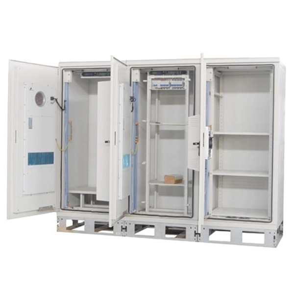
This guide highlights five top-rated options, detailing their tech specs, durability, and ease of use. Each entry provides a quick overview so you can compare sizing, IP ratings, and mounting features before choosing. Limitations of “Dumb” Waterproof Boxes + “Smart” Indoor Switches: Many attempt to achieve outdoor automation by placing an indoor smart switch inside a generic waterproof outdoor electrical box. This creates several problems: —Signal Degradation: The metal or thick plastic of the outdoor box can. We specialize in creating custom NEMA enclosures tailored to your exact needs. Browse our durable lineup of outdoor electrical enclosures designed to protect sensitive components from rain, dust, UV exposure, and harsh environmental conditions. Built for rugged reliability, these enclosures are. Exterior electrical boxes are weatherproof enclosures that protect outdoor electrical connections from moisture, dust, and impact damage. Here's what you need to know: Key Features to Look For: Top Applications: Whether you're adding a new outdoor outlet for holiday lights or upgrading an existing. Discover the 5 best outdoor electrical junction boxes for weatherproof protection. Compare features, materials, and ratings to ensure safe, code-compliant installations. When you're running electrical wiring outdoors, proper protection isn't optional—it's essential for safety and code compliance. Each option balances.
[PDF]
This document provides the users of USB4000 Spectrometers with instructions for setting up, calibrating and performing experiments with their spectrometer. Remote fiber optic spectroscopy is a sophisticated technique that uses fiber optic couplers, cables, and accessories to analyze samples at a distance from the spectrophotometer. The technique unlocks a range of experiments that standard UV-Vis or fluorescence instruments cannot accommodate. The. Fiber optic spectrometers have revolutionized the field of remote sensing and data acquisition, providing unprecedented flexibility and precision. These devices utilize the unique properties of fiber optics to measure and analyze the spectral composition of light, making them indispensable tools in. The Cary 60 Fiber Optic Coupler and the Cary 60 Dip Probe Coupler are optional accessories for the Cary 60 UV-Vis spectrophotometer. Both accessories convert the Cary 60 UV-Vis into a remote fiber optic measurement system. Contains descriptive. Near-Infrared Spectroscopy (NIR) offers important advantages in analytical chemistry, particularly in process monitoring and quality control across various industries. This paper details the operational principles, methodologies, and significant advancements in NIR spectroscopy, emphasizing the. The basics of fiber optic cables and bundles and how they can be used to collect and direct light are discussed in 'An Introduction to a Spectrometer: Fiber Optic Bundles'.
[PDF]
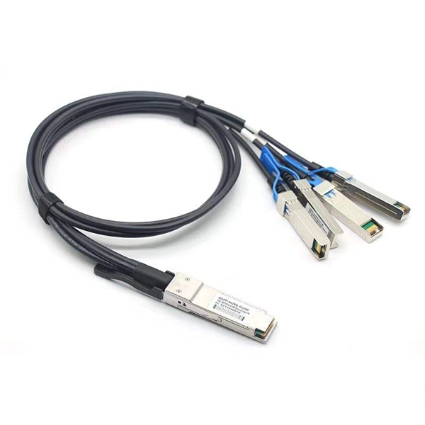
It performs error detection and alarm monitoring, serving as an essential tool for bit error testing in R&D and production of optical modules/ devices. Bit Error Ratio Tester is an instrument used to test and analyze bit error ratio in digital transmission systems, fiber optic communication systems, and digital microwave communication systems. Dimension Technology's BERT800 bit error tester series offers a comprehensive solution for testing and verifying high-speed optical transceiver modules. OPTELLENT is a provider of broadband test and measurement solutions for communications. The Company's test & measurement solutions are used in product development, manufacturing. As transmission rates continue to accelerate, accurately measuring bit error rates in optical modules is crucial to ensure reliable performance. There are three interchangeable slot boards which include QSFP, SFP+ and SFP ports separately. QSFP, SFP+ and SFP ports follow QSFP MSA, SFP+ MSA and SFP MSA. The user interface allows you to individually monitor bit error rate, error count and timer by connecting to PC via USB cable. In high-speed digital communication systems, even the smallest bit-level error can compromise performance, reduce efficiency, or lead to costly rework.
[PDF]