652 single-mode fiber, G. 655 single-mode fiber has lower dispersion in C-band (1530nm~1565nm), so the function of the optical amplifier in this band can be maximized, and the core area of the fiber is larger. Compared with G. 652B single-mode fibers are not suitable for wavelength division multiplexing applications because of their water absorption characteristics. 655 fiber is designed to reduce the effects of chromatic dispersion and PMD compared to G. It has significantly lower dispersion characteristics, enabling longer transmission distances and higher data rates. Non-Zero Dispersion Shifted (NZDS): G. 655 fiber. G652 is currently the most popularly adopted single mode fiber, for which G652 is defined as Standard SMF. It has G652A, B, C and D four versions. G652A and B have a zero dispersion wavelength point at 1310 nm, which makes it a natural fit for operation in the 1310 nm band. However, they are not. Among them, G. D fibers possess higher performance than G. The more recent variants, G. D, feature a reduced water peak that allows them to be used in the wavelength region between 1310.
[PDF]
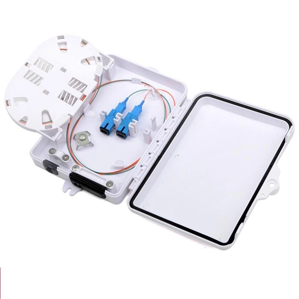
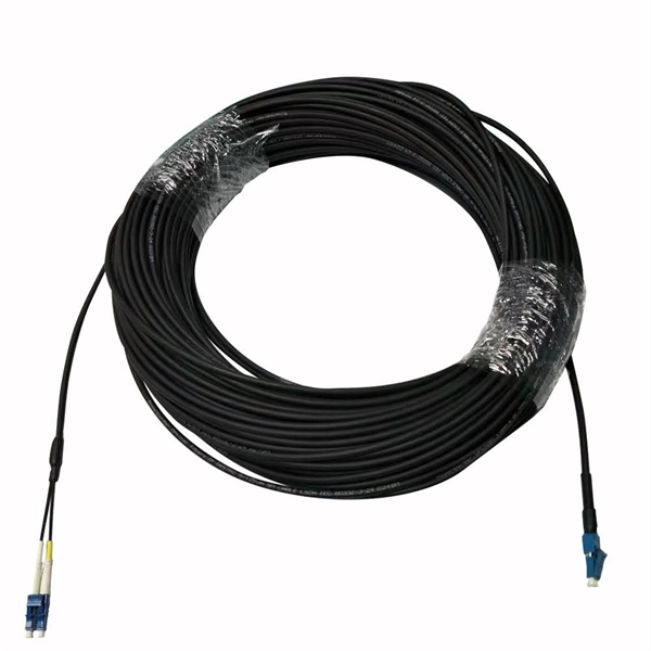
The drop cable connects your home, the patch panel organizes the network, the splice keeps connections seamless, and the optical splitter shares the signal with your neighbors. The fiber drop cable is what makes a true fiber-to-the-home (FTTH) connection possible. It's the final link in the chain that ensures you're getting the full, unfiltered power of fiber internet, not a mix of fiber and older technology. From the street to your living room, every piece of the fiber. To begin, the standard definition of splicing in optical fiber is joining two fiber optic cables together. The other, more common, method of joining fibers is called termination or connectorization. Splicing is most commonly used in the field but has application in cable assembly houses. Infield. In many applications of fiber optics, it is necessary to connect fiber ends (terminations) in some way such that light from one fiber can get into the other fiber without losing too much of its optical power. This creates a permanent and low-loss connection. Both techniques have their advantages and are suited for different applications, but understanding which method to use can greatly impact the network's. Many installations involve splitting the fibers in a cable or dropping a small fiber count cable from a large backbone cable. Backbone cables of 144-288 fibers are common and larger ones are becoming more common too. Drop cables are often only 2-12 fibers, meaning most fibers are continuing.
[PDF]
Instead of fusing one fiber at a time, mass fusion splicing can fuse up to all 12 fibers in one ribbon at once. Many of today's cables with high fiber count involve subunits of 12 fibers each that can be quickly ribbonized. Fiber optic joints or terminations are made two ways: 1) splices which create a permanent joint between the two fibers or 2) connectors that mate two fibers to create a temporary joint and/or connect the fiber to a piece of network gear. Either joining method must have three primary characteristics. Fiber optic splicing is the process of seamlessly joining two single Splicing has a lower optical loss and back-reflection than other terminations, making it the ideal choice for maintaining signal integrity and reliability in fiber optic networks. There are numerous use cases for fiber optic splicing. Through splicing, fiber optic technicians can extend the length of the fiber to make it long enough for use in a required cable run. As. To begin, the standard definition of splicing in optical fiber is joining two fiber optic cables together. The other, more common, method of joining fibers is called termination or connectorization. Splicing is most commonly used in the field but has application in cable assembly houses.
[PDF]
Fiber optic cables can be run anywhere from 2 kilometers to over 100 kilometers without signal regeneration, depending on the cable type and application. Fiber optic cable transmission distance is determined by two primary physical factors that affect signal quality as light travels through the fiber medium. The greater the distance, the greater. In this blog, I will discuss the fiber optic cable distance, the effect factors, how to choose the right fiber optic cables, and how to compare the transmission distances of single-mode and multimode fiber optic cables. Single-mode fiber (SMF) supports distances up to 40-100+ kilometers for standard applications, while multimode fiber (MMF) is typically limited. Fiber optic cables are the backbone of modern communications, enabling high-speed data transfer over vast distances. Unlike traditional copper cables, fiber optic cables use light to transmit data, resulting in faster speeds and greater bandwidth capabilities. Chromatic dispersion This is a key factor affecting single mode fiber distance. While this technology offers higher speeds and longer distances than traditional copper wiring, physical limitations impose distance constraints. Light pulses degrade as they travel over long spans, primarily.
[PDF]
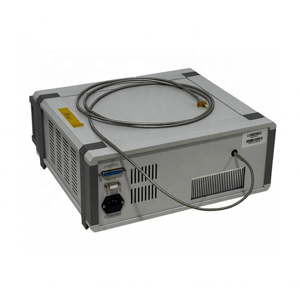
Stimulated Brillouin scattering (SBS) is often an unwanted loss mechanism in both active and passive fibers. Highly multimode excitation of fibers has been proposed as a novel route toward efficient SBS suppression. Here, we develop a detailed, quantitative theory which confirms this proposal and. To keep a smooth output beam, most techniques for mitigating optical nonlinearities are restricted to single-mode fibers. Moving out of the single-mode paradigm, we show experimentally that wavefront-shaping of coherent input light that is incident on a highly multimode fiber can increase the power. In high power applications of multimode optical fibers such as high power beam delivery and optical phase conjugation, the estimation of critical power of stimulated Brillouin scattering is important. Nevertheless, the estimations have taken no account of mode dispersion effect to date. In this. Suppressing Stimulated Brillouin Scattering in Multimode Fiber Amplifier With High Beam Quality Via Full-Field Wavefront Shaping S.
[PDF]
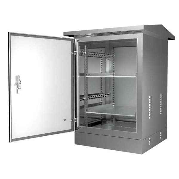
Industry standards such as the NEC (National Electrical Code) Article 770 and NFPA 70 provide binding requirements, while standards from IEEE and TIA offer additional guidance. When a fiber optic cable contains any of the following metallic elements, each must be bonded and grounded according to. NEC 2026 Article 750 consolidates grounding and bonding requirements for all limited-energy systems. Learn what changed, proper bonding methods, IBT requirements, and common mistakes to avoid. Grounding and bonding requirements for fire alarm, security, communications, and other limited-energy. This recommended practices document is a comprehensive manual for optical fiber construction and testing. Here are some highlights from Part IV of Article 770. The Code Making Panels (CMPs), composed of volunteers with full-time jobs, struggle to standardize and clarify terminology. Part I of Art. Although these are not current-carrying conductors, how and where you install them can affect “the practical safeguarding of persons and property from hazards arising from the use of. Understanding NEC Article 770 is the key to ensuring that optical fiber cables and raceways are installed safely, legally, and efficiently. This section of the National Electrical Code specifically addresses the unique characteristics and hazards associated with transmitting light for control.
[PDF]
In this post, you'll learn about the differences between one-tailed and two-tailed hypothesis tests and their advantages and disadvantages. I include examples of both types of statistical tests. In my next post, I cover the decision between one and. The design choice of double vertical fins and single vertical fins is not just for appearance considerations, but is deeply affected by the performance and purpose of the aircraft. This article will provide an in-depth analysis of the scientific principles and design logic behind the design of dual. Understanding the difference between one-tailed and two-tailed tests is crucial in determining the directionality of our hypotheses and the significance of our results. Join us as we unravel the intricacies of these tests and discover their applications in educational research. One-tailed tests look for an effect in a specific direction, such as an increase or decrease, while two-tailed tests consider effects in both directions. The alternative hypothesis parameter, commonly referred to as “one-tailed” versus “two-tailed” in statistics, defines the expected direction of the difference between control and treatment groups. In a two-tailed test, we assess whether there is any difference in mean values between the groups. The consequences in this example are extreme, but they illustrate a danger of inappropriate use of a one-tailed test.
[PDF]
Dual fiber modules use two fibers. They are easier to set up and give steady communication. They use a thin fiber core. They cost less and are. IntroductionEngineers, purchasing managers and installers often see the terms Transceiver, optical module and fiber optic module used interchangeably — and that causes confusion. This article answers the question directly and precisely: what each term usually means, where they overlap, and what. Optical modules and fiber optic transceivers are both essential components in fiber optic communication systems. Optical module: belongs to a. However, there are still many things that need to be paid attention to about how to link the optical fiber and the optical module. An optical module is a functional module, or an accessory. It is a passive device that cannot be used alone. It can only be used in switches and devices with optical.
[PDF]
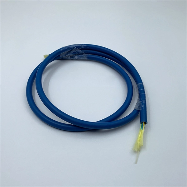
Multimode fiber has a larger core (typically 50 or 62. 5 microns) and can carry multiple light signals, usually LEDS, at once. While that's great for short distances, those overlapping signals can bump into each other and cause distortion over longer distances. This design makes them ideal for short to medium-distance communication and cost-effective installations. What is Multimode Fiber Cable? Multimode fiber (MMF) is an optical fiber designed to carry multiple light propagation paths—or. Multi-mode optical fiber is a type of optical fiber mostly used for communication over short distances, such as within a building or on a campus. Multi-mode links can be used for data rates up to 800 Gbit/s. Single-mode fibers allow only a single mode of light to propagate through the core, resulting in less signal dispersion and higher bandwidth capabilities. Single-mode fiber, as the name suggests, transmits a single light mode. It has a narrow core diameter of 8-10 microns and uses a laser or. They are typically more expensive than multimode cables, though, and there are different types of single and multimode fiber optic cables to consider, making the single mode vs. To help you decide on the type of cable you need for your.
[PDF]
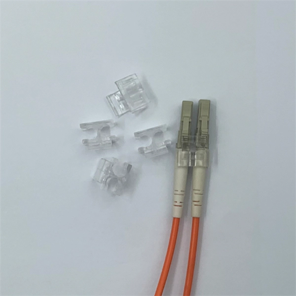
A fiber pigtail is typically a fiber optic cable with one end factory pre-terminated fiber connector and the other exposed fiber. It is usually suitable for field termination using a mechanical or fusion splicer. Executive Summary: A fiber optic pigtail is one of the most commonly specified yet least understood components in structured cabling. Get the wrong connector type, the wrong polish, or skip proper fusion splicing technique—and you're looking at elevated signal loss, increased back reflection, and a. A fiber optic pigtail is a short length of optical fiber —typically 0. The connector end is polished and tested under factory conditions, ensuring low insertion loss and high return loss. The connector end can be linked directly to network equipment, while the exposed end can be spliced to another fiber optic cable. Compared with quick termination or epoxy and polish connections placed on the field. Fiber optic pigtails are short, single, or multi-strand pieces of optical fiber cables with a connector on one end and exposed fiber on the other end. This essential function of pigtail fiber is.
[PDF]