ExxonMobil Guyana's fibre optic cable has landed, Guyana Vice President Bharrat Jagdeo said during a December 28 press conference. Ongoing construction of an offshore command centre at Ogle, East Coast Demerara, is expected to conclude this year. Prime Minister Bridgadier (Ret'd) Mark Phillips commissioned a new multi-billion-dollar direct submarine fibre-optic cable, marking a historic moment for the region and closing the long-standing digital gap between the coastland and the hinterland. The milestone ushers in gigabit-speed. ENet has completed a transformative multibillion dollar telecommunications project, landing the first ever direct submarine fiber‑optic cable to Bartica. This pioneering investment brings state-of-the-art fiber connectivity and 5G mobile service to the hinterland town, connecting Bartica directly. – PM Phillips says no region will be left behind in Guyana's digital transformation IN a ground-breaking development for Guyana's hinterland connectivity, Prime Minister Brigadier (Ret'd) Mark Phillips on Wednesday hailed the commissioning of the first-ever direct submarine fibre-optic cable to. Prime Minister Brigadier (Ret'd) the Honourable Mark Phillips hailed the commissioning of the first direct submarine fibre-optic cable to Bartica as a transformative development that brings the hinterland town in line with the capital city's digital capabilities. Speaking at the commissioning.
[PDF]
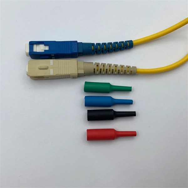
Fiber optic "cable" refers to the complete assembly of fibers, other internal parts like buffer tubes, ripcords, stiffeners, strength members all included inside an outer protective covering called the jacket. Cable provides protection for the optical fiber or fibers within it appropriate for the environment in which it is installed. You will also learn how different aspects of the product can affect budget and design. ■ The Five Key Parts of a Fiber Optic Cable A fiber optic cable. A fiber optic cable consists of five basic components: the core, the cladding, the coating, the strengthening fibers, and the cable jacket. When searching for a fiber optic cable, we need to pay attention not only to the connectors, such as SC to ST fiber cable, LC to SC fiber patch cable, or SC to. A TOSLINK optical fiber cable with a clear jacket. These cables are used mainly for digital audio connections between devices. This advanced cabling solution allows fast, secure data transfer and telecom over long distances. Understanding the components within a fiber optic cable enables. While fiber optic cable itself is cheaper than an equivalent length of copper cable, fiber optic cable connectors and the equipment needed to install them have typically been more expensive than their copper counterparts.
[PDF]
At present, key breakthroughs in optical fiber communication technology include high-order modulation formats, polarization multiplexing, wavelength division multiplexing, etc. Optical fiber communication can be widely applied in the fields of the internet and telephone networks . With the rapid development of cloud computing, big data, the Internet of Things, and other new technologies, we have entered an era of digitalization and informatization. The number of internet users has been steadily increasing, which has accelerated the exponential expansion of data services. A. Then the different technologies in optical fiber communication along with their features are discussed briefly.
[PDF]
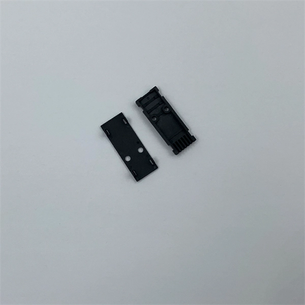
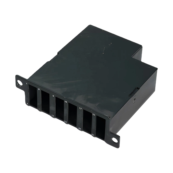
The V-groove substrate is the heart of the Fiber Array, providing precise alignment for the optical fibers. This substrate, typically made from silicon, glass, or ceramic, features a series of V-shaped grooves etched with sub-micron accuracy. Fiber Array (FA for short) is an array formed by installing a bundle of optical fibers or a fiber ribbon on the substrate at specified intervals by using a V-Groove (V-Groove) substrate. Fiber optic arrays in optical communications mainly include a substrate, a platen, and an optical fiber. Whether integrated into planar lightwave circuits (PLCs), optical switches, or high-speed transceivers, FAs play a vital role in ensuring. What is a Fiber Array (FA)? A Fiber Array, commonly abbreviated as FA, is a critical interface component in Silicon Photonics (SiPh) packaging, Photonic Integrated Circuits (PIC), and Co-Packaged Optics (CPO) architectures. It is responsible for efficiently coupling "external optical fibers" with. Fiber Arrays (FAs), as high-precision, high-performance optical components, have become indispensable core elements in fields such as optical communications, photonic integration, and laser processing. Typically, such an array is formed only for the very end of the fibre bundle, rather than over the entire length of the.
[PDF]
This fiber, known as non-zero dispersion-shifted fiber, has a small amount of dispersion in the 1550 nm operating window. This fiber type is widely used for transmitting multiple high-speed data channels across a single fiber in the 1550 nm range. Featuring a high-performance core design, these fibers deliver exceptional beam quality and low splice loss. The NuCOAT fluoroacrylate coating ensures superior environmental durability. That value determines whether the module is designed for multimode fiber (MMF) or single-mode fiber (SMF), how much attenuation the signal will experience, how dispersion behaves over distance, and whether optical amplification or DWDM systems are possible. Choosing the wrong wavelength can result. The F-SMF-28 Single-Mode Fiber from Corning (SMF-28e+) is all-glass and supports single-mode light propagation for a 1310/1550 nm operating wavelength. Optimized for access and metro networks, this fiber is compliant with Recommendation ITU-T G. Patch cables that incorporate these fibers are available from stock, see. This document outlines the specifications for a single-mode optical fiber and cable designed for use around the 1310 nm zero-dispersion wavelength, suitable for both the 1310 nm and 1550 nm regions, and compatible with analogue and digital transmission. It can be used in all cable constructions, including loose tube, tight buffered, ribbon, and.
[PDF]
Set up your Fiber Optic system with care. Do not make sharp bends. This helps signals stay clear and go farther. Make a plan to check your network often. Regular checks and cleaning help you find problems early. Fixing issues early keeps your. Fiber optic internet transmits data using pulses of light traveling through thin glass strands. The strength of this incoming signal must be measured precisely to ensure high-speed, reliable connectivity. The standard unit for measuring this optical power is the decibel-milliwatt, or dBm. Fiber optic networks are celebrated for their speed and reliability, but even the best systems can encounter problems. When issues like signal loss, slow speeds, or intermittent connectivity arise, systematic troubleshooting is key. This guide will walk you through diagnosing and resolving common. Signal loss in Fiber Optic networks can make data slow. You should fix it fast to get speed and stability back. > You can solve this with simple steps. However, various factors can cause signal degradation, leading to performance issues and reduced network reliability. They offer higher bandwidth, allowing more data to be sent simultaneously. The light-based communication system doesn't interfere with electromagnetic fields, reducing the risk of data corruption. However, in real-world installations, whether underground, aerial, or in harsh industrial environments, fiber cables can and do fail. Understanding the common causes of.
[PDF]
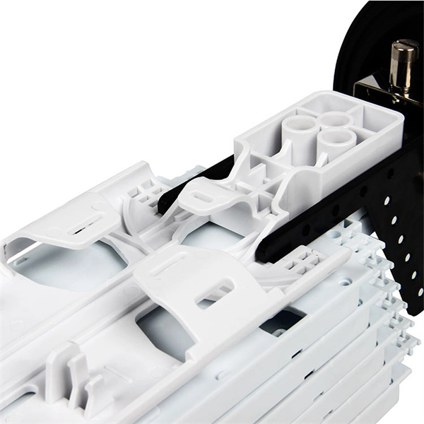
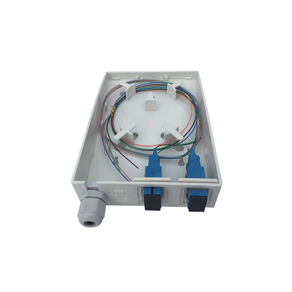
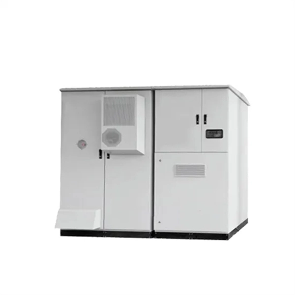
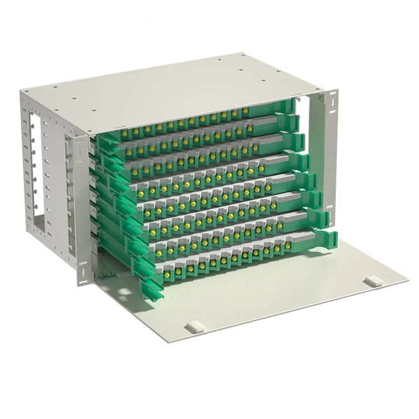
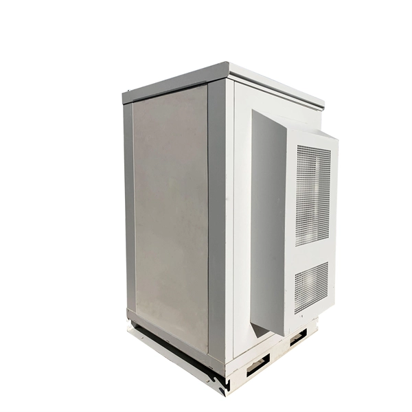
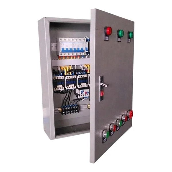
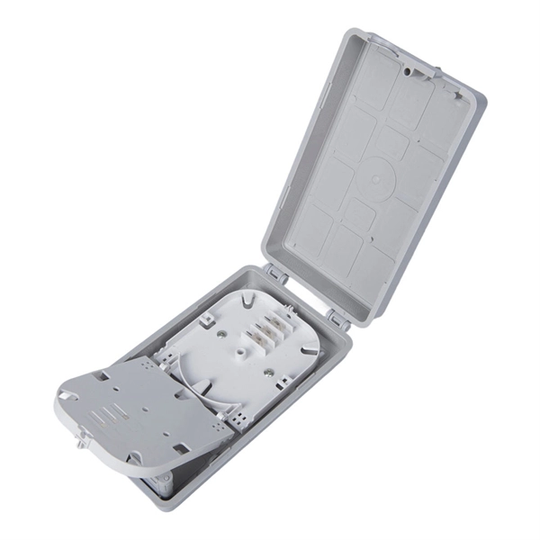
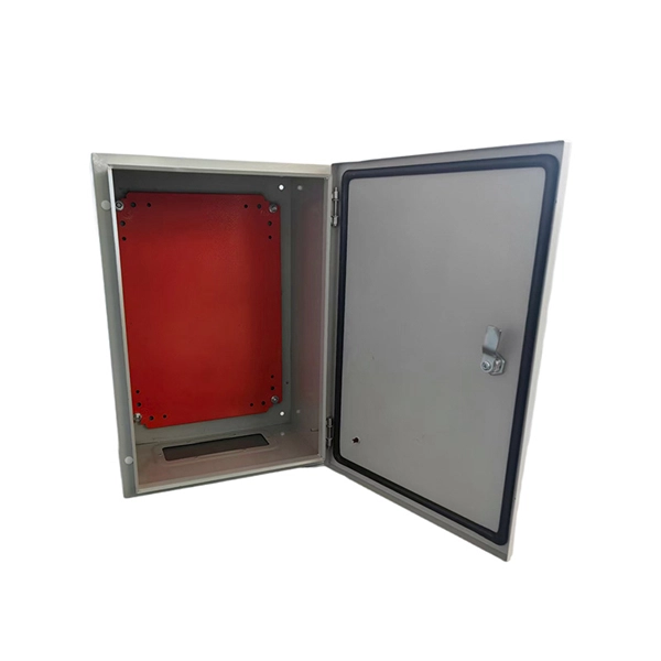
Learn how to install a fiber distribution cabinet step by step, including mounting, cable routing, grounding, and testing for FTTH networks. The installation of a fiber distribution cabinet involves five key steps: site selection, cabinet mounting, cable routing, fiber splicing, and grounding +. This step is very simple, we only need to install brackets on both sides of the optical fiber distribution box, and then fix the brackets to the designated position of the rack with screws. It should be noted that before installing the optical fiber distribution box, the installation direction of. Keeping this page as a placeholder for now. Have any questions? Talk with us directly using LiveChat. Read and understand this procedure (as well as the instructions provided with related assemblies) before beginning an installation. Do not discard this instruction; keep it on hand for future reference. Familiarize yourself to understand the unit's placement in your network. The 1U fiber optic distribution box is used as an example to introduce its structure. Three adapter panels can be installed on the front panel of this fiber optic distribution. Fiber Distribution Hub Installation Procedure - Optical Cable Corporation Products Fiber Copper Hybrid Cabinets, Racks, Enclosures Deployable Solutions Industries Oil & Gas Mining Industrial BroadcastAV Military Commercial Enterprise library & Support Contact Resources About OCC News Careers.
[PDF]
This paper describes a disruptive continuous monitoring system to detect Corrosion Under Insulation (CUI) risks for every meter of pipeline over large distances. Distributed Fiber Optic Sensing (DFOS) has emerged as a viable non-destructive ATEX-proof solution to detect CUI. ors by depositing metal coatings to the surface of the sensors. Three types of fiber optic sensors were investigated as candidates for corrosion detection: the extrinsic Fabry-Perot interferometer (EFPI), the absolute extrinsic Fabry-Perot interferomete (AEFPI), and the long period grating (LPG). This paper presents a distributed monitoring approach for detection, visualization, quantification, and warning for pipe corrosion using a single-mode telecommunication-grade fiber optic cable as a distributed sensor. The distributed sensor can be deployed on the surface of a pipe to measure. Fiber optic AE sensor was tested due to its anti-explosiveness, fitting to petrochemical plants. Experiment was successful, and one sensor could detect approx. 4,000mm-away corrosion. Our study attempts to detect. Experimental Investigation for Monitoring Corrosion Using Plastic Optical Fiber Sensors Liang Hou 1,*, Shinichi Akutagawa 1, Yuki Tomoshige 2and Takashi Kimura 2 1Department of Civil Engineering, Kobe University, 1 -1, Rokkodaicho, Nadaku, Kobe 6578501, Japan; cadax@kobe-u. jp 2Engineering.
[PDF]
The QSFP28 transceiver provides 100GBase-BX throughput up to 20km over single-mode fiber (SMF) using a wavelength of 1310nmTx/1280nmRx via an LC connector. This bidirectional unit must be used with another transceiver or network appliance of complimenting wavelengths. Whether it's building a network or upgrading an existing network, the Cisco® QSFP-100G-B20U4-I and QSFP-100G-B20D4-I transceivers provide 100G connectivity for platforms at up to 20km on single SMF (Single Mode Fiber). This. The QSFP-100G modules are our latest generation of 100G transceiver modules solution based on a QSFP form factor. Table 1 describes the Cisco QSFP-100G portfolio. Cisco QSFP-100G Portfolio The Cisco 100GBASE-SR4-S QSFP Module supports link lengths of up to 70m. To meet the demand for long-distance transmission in scenarios where optical fiber resources are scarce in edge access networks, Walsun has launched the 100G QSFP28 ZR4 BIDI product, and will demonstrate 100G 80km single-fiber bidirectional service transmission at OFC 2024. 66nm-RX) via an LC. NEC's 100G QSFP28 BiDi optical transceiver enables the transmission and reception of 100Gb/s high-speed data over a single optical fiber. By enabling bidirectional transmission over a single fiber, this module enhances fiber utilization efficiency and can reduce fiber costs. ZR4 BiDi, using four.
[PDF]
45 Jobs Laying Optic Fiber Cable jobs available on Indeed. Apply to Lineperson, Splicer, Optical and more!. Building a fiber optic network is a highly technical yet vital process that enables communities and businesses to access high-speed, reliable fiber optic internet. From the initial site survey to the final fiber to the home (FTTH) connection, every stage requires careful planning, coordination, and. Optical Fiber Cable Engineering Construction: A Comprehensive Operation Guide 1. Introduction Optical Fiber Cable engineering construction refers to the process of designing, planning, executing, and maintaining communication system infrastructure by deploying optical cables and associated. At the FOA, we're mainly concerned with communications fiber optics - telco, CATV, LAN, industrial, etc., but fiber optics are also used in medical or nondestructive testing inspection and lighting. Even within communications applications, we have applications that differ widely in usage and in. Starting with site surveys and permissions, to installing fiber optic cable and emphasizing the process as a key stage in mastering fiber optic installation, to the careful handling of cables and high-stakes splicing, each stage is critical. Discover the exact steps, adhere to stringent safety. The Fiber Optic Association, Inc. The method covers the steps from receiving the materials on the installation site and cable pulling as per the approved shop drawings.
[PDF]
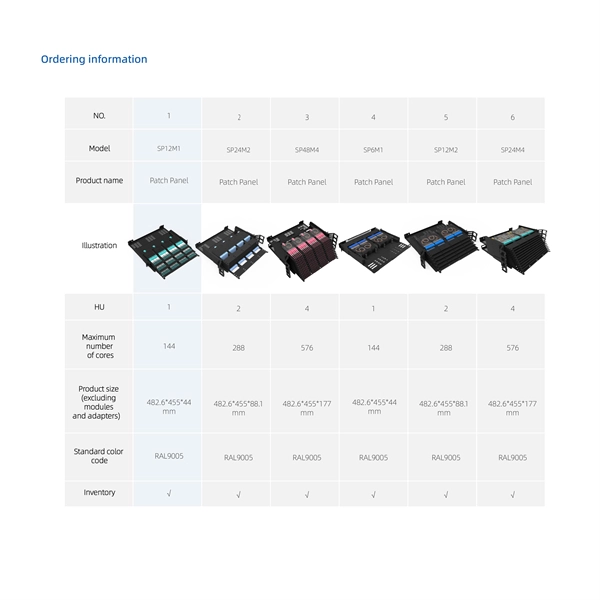
This AutoCAD DWG file shows a detailed layout for a fiber distribution terminal. It covers cable management, component positioning, and network planning, providing a clear guide for engineers and designers to implement organized and efficient fiber optic systems. For network planners and telecommunication engineers, the 24-Core Fiber Optic Distribution Box (FDB) is a foundational component in Fibre-to-the-X (FTTx) network deployment. MechStream is excited to offer the definitive drawing of this high-capacity distribution hub as a vital free download. This. Download CAD block in DWG. Fiber optic network design (896. 83 KB). Search by part number or description such as CAT5, CAT6, OSP, etc. Sort by any of the table headers. Use the drop down menu to filter by product category and type. Sort by any. 24T Fiber Optic Patch Panel AutoCAD Block AutoCAD drawing featuring detailed plan and elevation views. AutoCAD drawing featuring detailed plan and elevation views of a 24T Fiber Optic Patch Panel. This exclusive resource, alternatively recognized as a fiber distribution panel or optical. Fiber optic distribution in a metrobus station. Already Subscribed? Free download Optical fiber in DWG format or CAD block.
[PDF]
For singlemode fiber, the loss is about 0. 5 dB per km for 1310 nm sources, 0. 5 dB/km at either wavelength for outside plant max per EIA/TIA 568)This roughly translates into a loss of 0. 1. To be able to judge whether a fiber optic cable plant is good, one does a insertion loss test with a light source and power meter and compares that to an estimate of what is a reasonable loss for that cable plant. The estimate, called a "loss budget" is calculated using typical component losses for. Manufacturers provide a fiber loss factor in dB per kilometer. Total fiber loss is calculated by multiplying the distance by the loss factor, considering the actual cable length. 25 dB/km (@1550nm) and 0. Understanding where those losses come from, and how to calculate them, is essential for designing a link that actually works. The decibel is. A loss budget in fibre optics is a detailed accounting of every potential source of signal attenuation (loss) in a fibre optic link. By accurately calculating and managing loss budgets, engineers and technicians can guarantee that optical signals reach their destination with enough power to be. After measuring the loss of a fiber link, you now have to determine if that fiber link loss is acceptable or not. Here are the details and instructions about each field and how they contribute to the calculation: 1. Attenuation Coefficient (dB/km): This value represents the inherent signal loss per kilometer of.
[PDF]
Precision Fiber Products, Inc. offers a wide range of fiber optic products. We specialize in fiber optic interconnect components, including fiber optic cables, connectors, cable splicing, ferrules, and more. Ready to get started? Get a quote now!. AFL - Fiber optic cable, transmission and substation accessories, outside plant equipment, connectors, fusion splicers, test and inspection equipment. All of them must be unwound, guided, combined, wrapped, filled, or rewound under controlled tension. Without proper tension. Sign up for our newsletter to receive specials and up to date product news and releases. The dead end sets have the main function to fix the fibre optic cables to poles or metallic towers. On this splice is assembled the dead end. OPGW cables, the lay direction of the protection splice is the opposite to the. Used to fix ADSS (All-Dielectric Self-Supporting) optical fiber cables on tension towers or terminal towers, bearing the cable's tensile force to maintain stability within the tension section. This function is critical for preventing cable sagging or disconnection at tower endpoints, ensuring the. Fiberoptics Technology Inc. is a leading global supplier of standard and custom designed OEM non-telecom fiber optic components. We are headquartered in the United States, where we run three shifts and maintain the largest fiber production capacity of any fiber optic manufacturer in North America.
[PDF]
This paper investigates the intrusive effect of embedding optical glass fibers carrying FBGs on adhesive bond strength and adhesive layer thickness and quality. Optical glass fiber with inscribed fiber Bragg gratings (FBGs) is a promising technology for a SHM system. Embedding the optical glass. Carbon-fiber-reinforced polymer (CFRP) composites have many advantages, and have been widely used in aerospace structures, buildings, bridges, etc. The analysis of dynamic response characteristics of CFRP composite structures is of great significance for promoting the development of smart composite. Based on the example application of Emmenbridge, a newly built steel-concrete-composite bridge in Switzerland with 47 m long built-in carbon fiber reinforced polymer (CFRP) prestressing cables, we will present and analyze the process chain leading to a reliable surveillance of modern civil. 📦 For purchasing, use the RP Photonics Buyer's Guide for fiber Bragg gratings. It provides an expert-curated supplier directory, buyer-focused technical background information, and structured selection criteria to support professional procurement decisions. What is a Fiber Bragg Grating? What is a.
[PDF]
This setup lets OTDRs and fault locators analyze attenuation and connector loss at both ends of the fiber optic cable. Always stabilize your optical sources and verify the power meter calibration at each test wavelength. Clean all connectors, adapters, and jumpers. An OTDR works by transmitting high-power light pulses into the fiber and measuring the light reflected from any event or the end of the fiber due to a change in the refractive index. A small portion of the pulse light is also scattered due to impurities in the fiber, known as backscatter. The OTDR. Optical Time-Domain Reflectometer (OTDR) testing plays a central role in fiber optic maintenance and troubleshooting. By pinpointing faults and measuring network integrity, OTDRs provide invaluable data for both installation teams and maintenance engineers. This guide dives deep into OTDR technology, its applications, and how it integrates with modern components like optical transceivers. OTDR settings are a balance between dynamic range, acquisition time, spatial resolution and accuracy. To minimize testing time, compromises must be made on accuracy (detecting low loss. Frequently Asked Questions On OTDRS And Hints On Their Use OTDRs, also known by their technical name optical time domain reflectometers, are valuable fiber optic testers when used properly, but improper use can be misleading and, in our experience, lead to expensive mistakes for the contractor.
[PDF]