In this Shorts video, watch a step-by-step demo of installing riser bus bars and terminating MW cable joints for industrial electrical systems. Learn pro techniques for secure, durable connections and flawless finishing. Perfect for electricians, engineers, and electrical. Busbars are the unsung heroes of electrical panels, ensuring reliable power distribution and minimizing clutter. If you've ever wondered how to achieve a flawless busbar installation, you're in the right place. This guide will walk you through every step of the process, from selecting the right. These guidelines govern the busbar processing and installation procedures for all low-voltage switchgear and power distribution enclosures manufactured by our facility. The principles outlined herein encompass a comprehensive range of busbar fabrication techniques, including but not limited to. NOTE: Repeat the above operations each time a switchboard cubicle is placed. For standard torque values, refer to Standard Tightening Torques and comply with the specified torque values. Currently, Thor is the Technical Department Manager at Weisho Electric Co. Every step is crucial when installing high and low voltage. Learn how to install TE Connectivity's Raychem high voltage busbar insulation tape (HVBT). It is a heat-shrinkable, adhesive-coated tape which provides insulation enhancement and protection against accidentally induced flashover. Video is not currently available for playback.
[PDF]
The article provides an overview of protective relaying principles and their applications for high-voltage power system components. It covers the protection methods for generators, transformers, buses, and transmission lines using various relay types to detect and. Protective relaying is the backbone of fault detection and system isolation in As transmission systems grow increasingly complex with integration of renewables and smart technologies, the design, configuration, and application of protective relays have become more critical than ever. This article. tensify their search for reductions in capital investment and operating expenses. Faced with the continuing demand for more and more power in an environmentalist era, many operating companies are seeking, among other things, a means for supplying eliable power with fewer transmission lines and. SIPROTEC 7SD82 provides compact, cost-optimized line differential protection for medium- and high-voltage systems. It ensures safety with 3-pole tripping in 19 ms and high availability via conformal coating. The modular SIPROTEC 7SD86 is specifically designed for line differential protection of. Still deciding? Get samples first! Order sample Still deciding? Get samples first! Order sample. In HV (High Voltage) and MV (Medium Voltage) substations, relay protection safeguards critical assets such as transformers, circuit breakers, and lines. Effective relay protection depends on.
[PDF]
This Technical Brochure describes the induction phenomena (inductive, capacitive and conductive) that can lead to presence of voltage and currents on disconnected cable systems. The optical fiber composite overhead ground wire (OPGW) has been widely used in power transmission lines. Methods of calculation to evaluate those values and touch voltages are detailed and analysed, associated with various. working on cables u al, photocopying, recording or otherwise, without the prior written or use by members of the Energy Networks Association to take account of the conditions which apply to them. Advice should. Literature review: An in-depth literature review covering the modelling and calculations of the conditions relating to faults caused by interactions between fibre optic cables and power cores in submarine cables. Examples of electrically conductive installations where induced voltage may occur could be: • Overhead lines or cables out of opera- tion •.
[PDF]
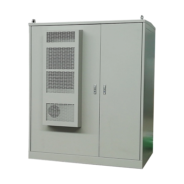
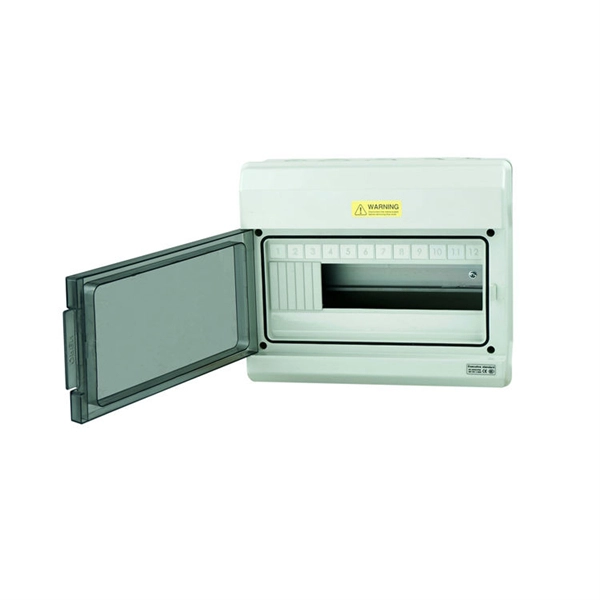
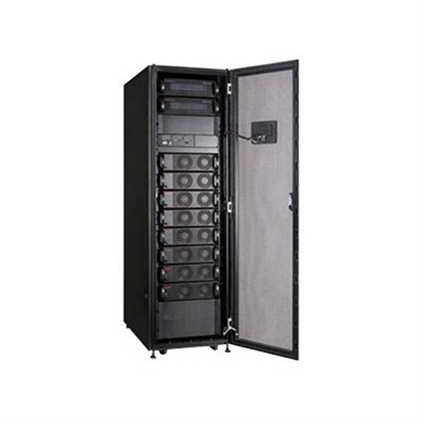
High voltage distribution cabinets are essential components in power delivery systems. They serve as the backbone of electrical infrastructure, ensuring safe and reliable distribution of electricity across various sectors. Dongshengyuan Electronic (DSY) provides high-quality power distribution cabinets that meet IEC, IEEE, and ISO certifications. As the energy landscape evolves, these cabinets are becoming more. Isolating switches are mainly used to isolate power supply, completely disconnect high-voltage maintenance equipment from live equipment, form a clearly visible disconnection point, and provide solid protection for the personal safety of maintenance personnel. It should be noted that the isolating. The high and low voltage distribution cabinet is usually connected with high-voltage or low-voltage cables. It is used for power stations, substations and other facilities. It uses high-voltage cabinet, and then depressurizes through the transformer to a low-voltage cabinet, and then to each power. The Incoming Cabinet is the first stop for electrical energy entering the power distribution system. Its main task is to carry the total load and provide a disconnection point. They play a crucial role in ensuring safety, efficiency, and longevity.
[PDF]
Abstract: Detecting partial discharges in cable joints is critical for timely defect identification and reliable transmission system operation. The electric field distribution of the optical fiber-implanted cable joint was simulated, followed by electrical performance tests, demonstrating that optical fiber implantation had a negligible effect on the electrical properties of the cable joint. A platform utilizing Mach–Zehnder–Sagnac. The results show that the average sensitivity of the sensor in the 10 kHz–80 kHz range is 71. 0 dB higher than that of the piezoelectric transducer, with a maximum signal-to-noise ratio of 65. To improve the long-term reliability and sensitivity of the sensing system, a novel method for cable joint monitoring based on implanting optical fibers. However, there is an industry gap in the literature about the highly sensitive fiber optic-based PD solution based on the acoustic emission principle. This paper aims to fill such an industry gap. In this paper, the fiber optic-based PD sensing (OptiFender) technology is applied to monitor the PD.
[PDF]
CRU provides comprehensive, accurate and up-to-date price assessments and research reports for bare optical fibre across various key regional markets, combined with insights into the factors and events affecting markets. Market Forecast By Mode (Single Mode Fiber, Multi-Mode Fiber), By End-Use (Telecommunications, Networking, IT & Data Centers, Broadcast), By Application (Telecommunication, Power Utilities, Medical, Industrial), By Fiber Type (Glass Fiber, Plastic Fiber) And Competitive Landscape How does. Based on our observations and market communication with upstream suppliers, the single-mode fiber market in China has experienced an unprecedented price surge in the first two months of 2026. This article summarizes the latest fiber optic price data as of March 9, 2026, along with the recent. According to APO Research, The global Fiber Optic Cables market was valued at US$ million in 2023 and is anticipated to reach US$ million by 2030, witnessing a CAGR of xx% during the forecast period 2024-2030. North American market for Fiber Optic Cables is estimated to increase from $ million in. How does 6W market outlook report help businesses in making decisions? 6W monitors the market across 60+ countries Globally, publishing an annual market outlook report that analyses trends, key drivers, Size, Volume, Revenue, opportunities, and market segments.
[PDF]

Discover the key differences between optical fiber cables and copper cables. OPTRAL analyzes the advantages and disadvantages to enhance connectivity. Optical and copper interconnection technologies represent two distinct approaches to data transmission, each with its own advantages and limitations. While fiber optics dominate in performance, copper retains its technical and economic justification. But how do you decide which one is best suited for your needs? This article delves into the technical comparison between copper and fiber optic cables. When it comes to modern data transmission, Fiber Optic cables and Copper Cables play pivotal roles in ensuring seamless connectivity. What Are Fiber Optic Cables? Fiber Optic cables function by transmitting data in the form of light pulses through optically pure glass fibers. These fibers are. “Fiber offers multiple technical advantages, including exceptional bandwidth, low attenuation and distortion over long distances, reduced bulk, as well as isolation from electromagnetic interference (EMI) and electrostatic discharge (ESD). ” Let's explore the characteristics, advantages, and. The two core material technologies used in almost all cables are fiber optic, and copper wiring. Whether you're looking at an HDMI cable, a USB cable, Ethernet patch cable, or any other kind of network of data transmission cabling, they are all built using copper or fiber optic internal wiring.
[PDF]
Fiber optic cables are often perceived as being fragile and prone to breakage, but this is not entirely accurate. While it is true that fiber optic cables can be damaged if they are bent or flexed too much, they are actually quite durable and can withstand a significant amount of. This cable is mainly used for interconnecting cable for jumpers, patch cords or pigtails. Tensile Loading (N) NO. This cable is mainly used for interconnecting cable for. Cablers have very little influence on the majority of causes of cable field failures. While a small percentage, we can examine the “intrinsic” cable failures and what is done to prevent them. Does the glass inside the cable degrade? Break? What are the cables expected to withstand through their. As the name suggests, FTTH butterfly optic cables are so - named due to their cross - sectional shape, which resembles the wings of a butterfly. These cables are a type of fiber optic cable specifically designed for use in FTTH networks, where they play a crucial role in delivering high - speed. Fragility: Optical cables are fragile and can be easily damaged if not handled carefully. They are sensitive to bending and twisting, which can cause signal loss or even breakage. Limited Compatibility: Optical cables are not compatible with all devices. The general assumption is simple: once installed, the cable does its job – transmitting data from point A to B – and that's it.
[PDF]
This guide highlights essential precautions including wearing protective gear, disconnecting power sources, handling fiber scraps carefully, avoiding face or eye contact, following regulatory standards, using adequate lighting, and keeping food or beverages away from work areas. Installing fiber optics in your home or workplace is a great way to increase your network's overall speed and bandwidth. But installing them can be a problem for inexperienced installers. However, it would be best if you had simple techniques to install fiber optics smoothly and efficiently. Here. Fiber optic cable installation is a critical process that impacts the performance and reliability of the entire network. Whether you're installing fiber for a new construction project or upgrading an existing network, proper installation is essential for achieving the best results. Improper. What happens if you follow the guidelines for installing fiber optic cable? Follow the guidelines for fiber cable installations to avoid signal degradation, increased attenuation, and potential damage to the cables or connectors. This includes pulling tension, minimum bend radius and crush loads. Installers must understand these specifications and know how to pull cables without damaging them. Following these.
[PDF]
Since fiber-optic cables use light to transfer data instead of electricity they actually generate less heat than traditional cables! This absence of heat makes them less likely to catch fire and less of a fire hazard than normal metal wires. A rigorous analysis of optical power density, thermal ignition mechanisms, and the role of Automatic Laser Shutdown in preventing fire hazards in EDFA-amplified fiber networks. Article Inspiration This article was inspired by the Fiber Optic Association (FOA) March 2026 Newsletter — Seen On The. Myth #1 – Fiber-optic cables are a fire hazard. The general assumption is simple: once installed, the cable does its job – transmitting data from point A to B – and that's it. Understanding the safety hazards that go with fiber optic cable is critical for those who install or maintain fiber optic systems. As electrical professionals, most of us take fiber optic (FO) safety for granted. Since fiber optic cable carries no electricity, we don't worry about electrocution. This means they won't produce sparks or arcs that could ignite a flammable atmosphere. In a Class I Division 1 or Zone 1. Fiber-optic cables are the backbone of modern connectivity—powering 5G networks, global internet backbones, and data center interconnections with near-light-speed data transmission. While these cables are engineered for durability (with some rated to last 25+ years), they are not invulnerable.
[PDF]
While fiber itself is constructed of thin, fragile filaments of glass, fiber cables that are laid outdoors are built for durability. Fiber optic internet represents a significant leap forward in broadband technology, offering speeds and reliability far exceeding traditional cable or DSL connections. Unlike older technologies that rely on electrical signals transmitted through copper wires, fiber optics use thin strands of glass. Unlike traditional copper wires that carry electrical signals, fiber optics use thin strands of glass or plastic to transmit data as pulses of light. This fundamental difference is the key to its superior speed, bandwidth, and reliability. The light signals travel at near the speed of light. Installing fiber optic cables underground involves far more than digging trenches and placing cables. It forms a critical backbone for modern communication networks across both urban and rural environments. Unlike traditional copper systems, fiber optic cables require specialized handling techniques and precise installation methods to. In our digital age, high-speed internet and reliable communication networks are powered by fiber optic cables, which transmit data as light signals at incredible speeds. However, the performance of fiber optic technology depends heavily on proper fiber optic cable installation.
[PDF]
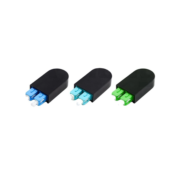
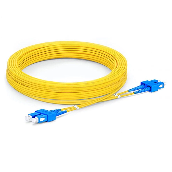
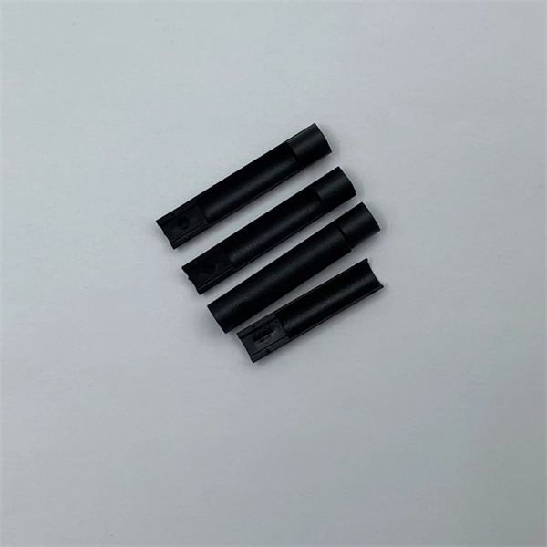
The other side of the pigtail is open and is connected to a fiber optic cable. This creates a stable and reliable connection between network equipment. They are the bridge between fiber optic cables in the field and the equipment or patch panels that manage them. By combining factory-installed connectors with spliced bare fiber, pigtails ensure that network installers can create fast, reliable, and cost-effective terminations. DINTEK supplies this equipment, but the pigtails can also be. In the intricate ecosystem of fiber optic networks, two components play a critical role in ensuring seamless connectivity: patch cords and pigtails. A fiber optic pigtail is a type of fiber optic cable with only one end that has a factory-terminated connector and the other end exposed as bare fiber. When compared to field-installed rapid. Today, I'll show you how to pick the right patch cord or pigtail — step by step. You plug it into a switch, router, or patch panel. It's ready to use out of the box. A pigtail is for splicing.
[PDF]
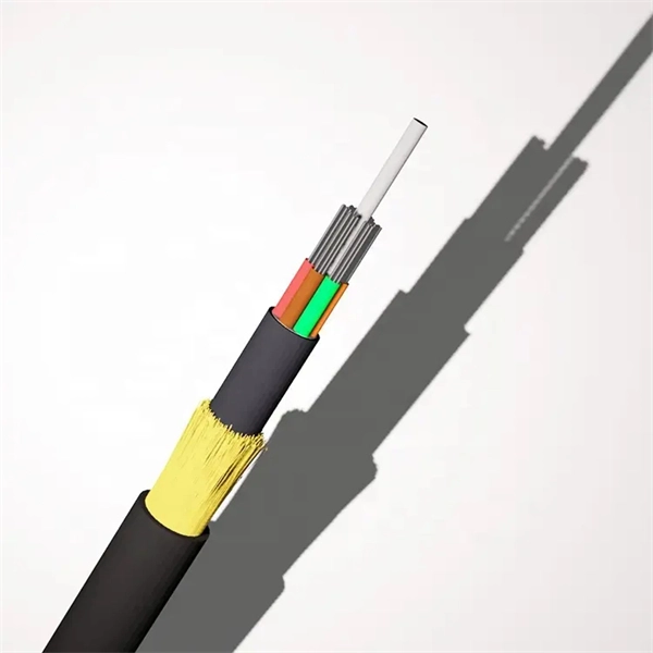
A practical, engineering-focused guide to planning and installing underground fiber optic cables with the right cable structure, trench design and protection level for long-life, low-risk networks. Match trench method with the correct underground fiber structure (GYTS . Installing fiber underground is one of the most durable ways to protect a network's backbone — when it's done right. Direct-burial fiber cable eliminates the need for continuous conduit runs and can be faster and more cost-effective on long, open runs. But because the cable sits in soil exposed to. 1. 01 This procedure provides general information for the installation of Prysmian fiber optic cables in direct buried applications. The methods described are intended for guideline use only, as it is impossible to cover all the various conditions that may arise during an installation. Individual. ion) and “ Installed” (after installation). The following formulas may be used to determine general guidelines for installing Corning Optical Communications fiber optic cable; however, refer to the cable specifi simply double the minimum working bend radius. Split cable guides and split 40-in. Fiber optic cable transmits data as pulses of light through thin strands of glass, offering superior bandwidth and distance capabilities compared to traditional copper wiring.
[PDF]
Fiber optic cables are also more secure, as they are harder to tap or hack. Fiber and copper cable repair both require trained splicers, but the tools, techniques, and failure modes are completely different. Sending a fiber splicer to repair a copper cable - or vice versa - wastes time and risks making the damage worse. Here is what you need to know before you call for. Well-made fiber optic cables are very tough, making them great choices for homeowners who would like to limit weather-related internet outages as much as possible. The comparatively high durability of fiber optic cables comes from a series of factors, including: The quality of the glass cables, of. Copper and fiber optic cables each offer distinct advantages and disadvantages that can impact performance, cost, and long-term efficiency. But how do you decide which one is best suited for your needs? This article delves into the technical comparison between copper and fiber optic cables. Fiber optic cables are typically damaged in one of two ways: A premade fiber optic cable suffers connector damage when too much pull-force is applied during installation. This can occur on long cable runs through tight conduit or duct, and also if the cable becomes caught or snagged.
[PDF]
This guideline defines the requirements and standards for design of underground electrical and telecommunication pathway systems. The guideline covers concrete encased duct banks and manholes for primary (medium voltage) power distribution cables and telecommunications. The UGS Manual provides guidance and standards pertaining to installing and working with underground structures for electrical facilities. Also included are. The purpose of this Distribution Standards manual is to provide the basis for standardized, uniform, and consistent engineering, construction and maintenance practices for the Nashville Electric Service (NES) system. The contents of this manual contain minimum requirements used in designing and. This section contains the requirements for equipment and installation (including manholes, switch vaults and pull boxes) relating to the Sub-transmission, Distribution, and Control of electric power ranging from 600-Volts to 25,000-Volts, such as substations, switchgear, circuit breakers, and. stent and reliable underground power distribution system. These standards are required to be used by anyone who is involved with design or installation of underground power distrib ion systems within the St. George City service territory. All high voltage, 600 volts or higher, underground power. FILING INSTRUCTION: This bulletin replaces RUS Bulletin 1728F-806, Specifications and Drawing for Underground Electric Distribution, dated June 2000.
[PDF]