Typical project ranges for fiber optic cable per meter span from a low of roughly $0. 65 to a high around $5. 00, depending on type, protection, and installation needs. The majority of projects cluster in the $1. 60 per meter range for standard indoor runs with simple. Fiber optic cable cost per meter varies by type (single‑mode vs multi‑mode), durability, and installation conditions. The main price drivers include cable grade, jacket material, pull tension, connectorization, and any required conduit or protection. The following coverage gives a practical price. Fiber-optic cable materials typically cost $1 to $6 per linear foot, depending on fiber count and cable type. Commercial building installations with 100-200 network drops generally range from $15,000 to $30,000. The type of fiber optic cable selected based on your requirements, length of installation, and number of fiber. Getting accurate cost estimates is crucial for winning fiber installation bids. Smart contractors know that underground vs aerial installation pricing varies wildly based on location and project conditions. We'll show actual costs for.
[PDF]
At the heart of every optical transceiver lie three essential components, often called the “Three Pillars” of optical communication: Laser — generates light. Modulator — encodes data onto the light. Photodiode — decodes light signals back into electrical form. As an essential component of optical fiber communication, optical modules are optoelectronic devices that facilitate the conversion between optical and electrical signals during the transmission process. Operating at the physical layer of the OSI model, optical modules are core devices in optical. An optical module usually consists of an optical transmitting device (TOSA, including a laser), an optical receiving device (ROSA, including a photodetector), functional circuits,main control circuit board (PCBA), housing and optical (electrical) interface and other components. Together, lasers, modulators, and. That is, metal medium communication represented by coaxial cables and network cables is gradually being replaced by optical fiber media. Composition of Optical Modules The optical module, known as Optical Transceiver in. This comprehensive guide breaks down the internal structure, core components (TOSA, ROSA, lasers), and operational mechanisms of SFP optical modules, enriched with technical insights and real-world applications. These modules typically consist of a transmitter, which converts electrical signals into a light signal, and a receiver, which converts the received signal back.
[PDF]
Optical modulators are used in optical communication systems to encode data onto light waves for transmission through optical fibers. The modulator encodes the data onto the light wave by modifying its amplitude, phase, or frequency. 📦 For purchasing, use the RP Photonics Buyer's Guide for optical modulators. It provides an expert-curated supplier directory, buyer-focused technical background information, and structured selection criteria to support professional procurement decisions. What are Optical Modulators? An optical. Optical modulators are devices that modify the properties of light, such as its amplitude, phase, frequency, or polarization, in response to an external signal. These devices play a crucial role in modern optics and photonics, enabling the manipulation of light for various applications. The beam may be carried over free space, or propagated through an optical waveguide (optical fibre). It acts as the “translator” between the electronic and photonic worlds. They enable the modification of optical wave characteristics such as the intensity, phase, polar-ization, and frequency of light signals. There are basically two types of modulators: bulk and integrated-optic.
[PDF]
As shown in the figure below, the main cable consists of three conductor wires extending from the top of the motor flat lead extension to the wellhead banded to the production tubing. The ESP cable carries current (amperage) from the motor controller at the surface down to the motor. CAVALCADE™ ESP power cable meets the high-quality standards required for any oil and gas industry specification–even the most challenging unconventional applications–to deliver the electrical requirements of your ESP and to extend system run life. Get cable built with solid copper conductors. Typically, it is banded or clamped to the production tubing from below the wellhead to the ESP unit because it is not designed to support its own weight. It is a specially constructed three-phase power. Levare is one of few artificial lift equipment providers manufacturing the complete ESP system including power cable. The total facilities capacity is approximately 10,000 kilometers (over 6,200 miles) of power and motor lead extension (MLE) cables annually. It is a specially constructed three-phase power cable designed. When performing well interventions, the choice of a suitable cable is critical to ensure well control is maintained while deploying wireline through pressure control equipment (PCE). Depending on the well conditions, many considerations should be taken into account for choosing the best cable.
[PDF]

This document provides a comprehensive technical overview of the Ring Main Unit (RMU), serving as a reference for power system design, selection, and maintenance. Ring Main Units (RMU s) and Medium Voltage (MV) Switchgear are crucial in MV power distribution. Globally, they each hold about half the market share. MV switchgear handles primary distribution for large industrial facilities and grid infrastructure. RMUs, however, shine in secondary distribution. RMUs are commonly used in secondary distribution systems, particularly in urban areas, industrial complexes, and commercial. Scope of Application: The Ring Main Unit (RMU) is a compact switchgear device used in medium-voltage power distribution systems (typically 10kV–35kV). Some of the key features of the RMU includes SF6 gas insulation, compact and modular construction, integral protection system, fully extendable options. SFA-RM units are designed for supplying reliable energy, protecting electrical equipment in secondary distribution networks up to 17. Their compact design makes them suitable for various network applications such. Loading. Company Introduction:The New Concept Electric Inc. (NCE) was founded in October 2001, with a registered capital of 57 million Yuan. The company now covers an area of 77, 601 square meters (116 acres), and has a building area of 80, 451 square meters.
[PDF]
The optical fibre sensors are divided into two categories: thrubeam and reflective. The thrubeam type comprises a transmitter and a receiver. The reflective type, which is a single unit, is available in 3 types: parallel, coaxial, and separate. The fibre optic sensor has an optical fibre connected to a light source to allow for detection in tight spaces or where a small profile is beneficial. The light beam travels through the core by. Fiber optic sensors are prevalent in various applications, from computers and printers to motion detectors. For instance, when a printer or copier door is open, light falls on the sensor, stopping the machine for safety. Fiber optic sensors use light properties to detect and measure physical quantities such as temperature, pressure, and displacement. Depending on the application scenario, different. Functional (all optical fiber type) optical fiber sensor Using optical fibers (or special optical fibers) with sensitivity and detection capabilities for external information as the sensor element, the sensor combines "transmission" and "sensation". During operation, the light source enters the optical modulation region through the incident fiber. The physical quantity to be measured (such as.
[PDF]

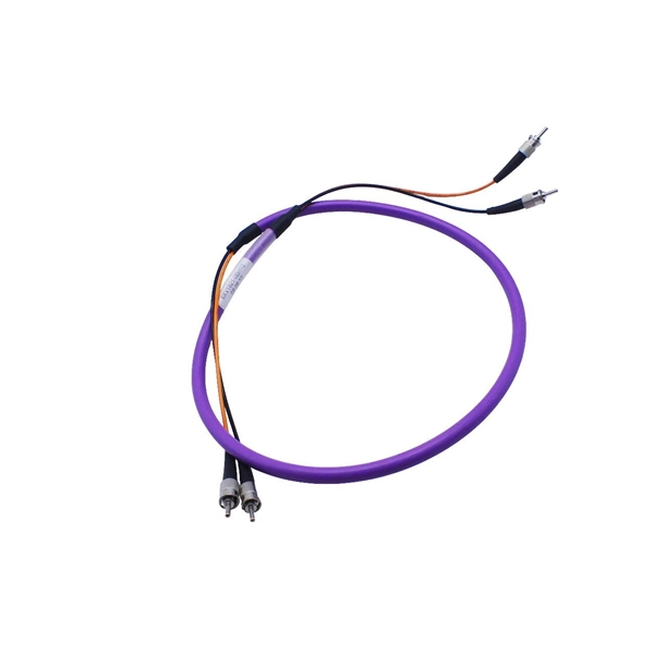
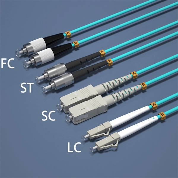
The most commonly used patch cable connectors today include FC, ST, SC, LC, MTRJ, and MPO connector types, as well as newer very small-form-factor (VSFF) CS, SN, and MDC connectors used in high-density, high-speed duplex data center environments. This guide will help you quickly understand the main types of fiber patch cords and how to choose the right solution for your project – and how ZION can support you with stable quality, flexible customization and global supply. What Is a Fiber Optic Patch Cord? A fiber optic patch cord (fiber. An optical fiber patch Cable is a jumper wire used to connect from equipment to an optical fiber cabling link, and it is usually used for the connection between an optical transceiver and a terminal box. It is widely applied in fields such as optical fiber communication systems, optical fiber. Fiber optic patch cords, also known as fiber optic patch cables or fiber jumpers, are indispensable components in modern optical networks. They act as the critical link for interconnecting devices like optical switches, servers, and distribution frames. Behind its slender appearance lies the fusion of core types, connector types, and polish levels, each chosen for a specific application. It is composed of fiber optic cable and fiber connector that fixed at both ends of optical cable, has been widely used in various fields such as fiber optic.
[PDF]
Summary : Fiber optic color codes are crucial for efficient, accurate, and reliable network installations. This guide explains how standardized fiber strands, cable jackets, connectors, and MPO systems simplify identification, prevent mismatches, and maintain signal. Tired of sorting poorly colored fibers? WolonFiber's 12-Color Fiber Optic Pigtail Packs are manufactured strictly to the TIA-598-C standard with vibrant, easy-to-identify colors. Perfect for fast, error-free termination in your ODF or splice closures. Following industry. You'll learn how to identify single-mode vs. multimode at a glance, trace individual strands in a 144-fiber bundle, and avoid the critical error of mixing connector types. In fiber optics, color isn't for decoration; it's a critical safety and efficiency tool. The TIA-598 standard (specifically. While labeling text offers specific details, color-coding makes it easy to identify cable uses or zones. In accordance with TIA-598-D standards fiber optic cables are based on the standard colors for jackets in single-mode: yellow, aqua/orange for multimode. 3 Create your own standards using colored.
[PDF]
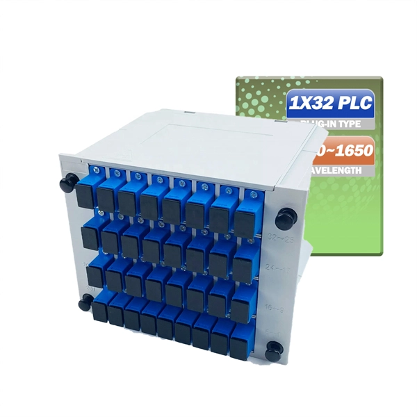
Optical splitters enable a signal on an optical fiber to be distributed among two or more fibers. Since fiber splitters contain no electronics nor require power, they are an integral component and widely used in most fiber-optic networks. A fiber optic splitter is a passive optical component that divides a single incoming optical signal into two or more outgoing signals, or combines multiple incoming signals into one. Unlike active devices (which require power), splitters operate without electricity, relying solely on the physics of. Optical cables, also known as fiber optic cables, consist of thin strands of glass or plastic fibers surrounded by a protective casing. These fibers transmit data as light signals, which are converted into electrical signals at the receiving end. The benefits of optical cables are numerous. A fiber-optic splitter, also known as a beam splitter, is based on a quartz substrate of an integrated waveguide optical power distribution device, similar to a coaxial cable transmission system. Its primary role is in Passive Optical Networks (PON), which are the foundation of. A fiber broadband provider typically determines and overall split ratio for the network, such as 1x32 or 1x64, and uses combinations of splitters to meet that ratio with each PON port. 1x32 splits were common in North America for G-PON architectures. As XGS-PON continues to be adopted, some service.
[PDF]
Diode lasers are compact, solid-state devices that generate coherent light from semiconductor material. They are constructed using materials like gallium arsenide (GaAs) or gallium nitride (GaN). SEM (scanning electron microscope) image of a commercial laser diode with its case and window cut away. The anode connection on the right has been accidentally broken by the case cut process. They operate by applying an electrical current to the semiconductor material, which stimulates the. What is a Laser Diode? A laser diode is a small, solid-state equipment that uses semiconductor material to produce continuous light. The laser can be made up of a single diode or a combination. Laser diodes come in various types, each suited for specific applications. The most common types include: Single-Mode Laser Diodes: Emit a single wavelength of light, ideal for high-precision tasks. VCSEL. The laser diode is a form of semiconductor diode that generates coherent laser light rather than the more usual incoherent light produced by other sources such as LEDs or other emitters, even though some of these produce a narrow band of frequencies. Semiconductor laser diode technology is in. The term LASER stands for Light Amplification by Stimulated Emission of Radiation. It functions similarly to an LED, but the key.
[PDF]
This chart guides how close workers can safely get to energized equipment based on system voltages and other factors, ensuring compliance with safety standards such as NFPA 70E. A distribution box, also known as a distribution board or panel, is the central unit that distributes incoming electrical power to various circuits. Each outgoing line can be individually. Working space: The front clearance, side clearance, and height clearance requirements for electrical equipment that provide a safe area for maintenance, inspections, and other work. Dedicated space: The space equal to the width and depth of electrical equipment in addition to the space extending. The National Electrical Code (NEC) provides comprehensive safety standards for electrical installations, including requirements for electrical panels (main service panels and subpanels or breaker box). NEC Article 408 covers switchboards, switchgear, and Panelboards installation and applications. Electrical clearances set the minimum safe distances for panels, overhead lines, pools, and buried wiring — and ignoring them has real consequences. They would have done better to use an LB or a gutter. The problem is the box has a rated fill and the wire has a bend radius. Maintaining a safe working distance from energized parts in electric power systems is critical to preventing electrical.
[PDF]
An AMR unit can be retrofitted onto an existing meter to automatically ping the meter and get a current reading. The meter data is transferred to a database where it can be monitored, analysed and used to bill customers based on actual consumption. An AMR (Automated Meter Reading) meter collects data from your gas, electricity, or water meter and transmits it to a central platform in real time. It eliminates manual readings and gives you instant access to consumption data. We offer industry-leading SmartPoint ® modules that read and store. With our Automated Meter Reading (AMR) systems, you can automatically capture water consumption and status data from water meters just by walking or driving by with mobile reading software that collects data and synchronizes with BEACON ® SaaS hosted software. One Comprehensive. The meter communicates to its collection point using 900 MHz mesh network topology. Automatic Meter Reading (AMR) Systems are technological solutions that enable the remote and automated reading of meter data for energy sources such as electricity. We support you with a powerful, modular radio technology that delivers high-frequency energy data - with stable transmission, long range and low maintenance. As a water and energy provider you need a flexible solution for remotely reading consumption meters that is tailored to your precise needs.
[PDF]
This video illustrates the step-by-step connection from the energy meter (KWH Meter) to the main Double-Pole MCB, the Neutral Link terminal block, and finally to the four individual Single-Pole Miniature Circuit Breakers (MCBs) for distribution to different circuits. In this guide, we will break down the key elements involved in connecting the main power supply to your home, providing a clear path for a successful setup. We will focus on the critical parts of the system, from basic components to step-by-step assembly procedures. Whether you are looking to. Always begin with disconnecting the main supply before accessing any enclosure containing distribution components. This prevents arc faults and ensures safety when modifying or inspecting current paths. Inside the service housing, line conductors from the utility feed typically enter through the. When it comes to electrical wiring, the connection between the meter and breaker box is crucial. This connection ensures that electricity is properly distributed throughout the building, allowing appliances, lights, and other devices to function. It shows the hot wire entering the meter lugs, the neutral wire connecting to the neutral bus bar, and the essential ground wire linkage to ensure system safety. Watch a simple and clear demonstration of how to wire a basic residential electrical setup. The diagram provides a clear and concise overview of how the meter is connected to the electrical.
[PDF]
An optical power meter is an electronic device that measures the power of an optical signal. It helps engineers verify the performance of optical fiber systems, ensuring that the signal strength meets requirements, and is an essential tool for communication network maintenance and. An optical power meter (OPM) is a device used to measure the power in an optical signal. Other general purpose light power measuring devices are usually called radiometers, photometers, laser power meters (can be. An optical power meter (OPM) measures the power levels of light signals in devices that transmit data or power using light. The term "optical power meter" may sound generic, but in popular usage, it specifically implies a fiber optic power meter. For light power measurements outside the field of. Optical Power Meters (OPMs) are crucial instruments in the field of optical sensors and fiber optic communications. It provides an expert-curated supplier directory, buyer-focused technical background information, and structured selection criteria to support professional procurement decisions. It measures optical power directly, and it is also used in loss testing when paired with a stable light source.
[PDF]
The most common causes of a fluctuating multimeter reading is due to a bad connection or loose wiring in the circuit. In order to investigate this possibility you will need to thoroughly inspect all of your connections and wires for any signs of oxidation, corrosion, fraying or. However, what happens when your multimeter starts behaving erratically, displaying fluctuating readings instead of stable values? This seemingly minor issue can lead to misdiagnosis, wasted time, and even potential safety hazards. Understanding the reasons behind a jumping multimeter reading is. The reading displayed on the meter is affected by factors like voltage drop across components in the circuit being tested. If this reading keeps jumping around unexpectedly it could indicate a problem in the circuit itself. Measuring Current: For current measurement, I switch the multimeter to the current setting. This method allows me to see how much current flows through. This guide delves into the various causes of multimeter fluctuations and provides practical solutions to ensure accurate. From fluctuating readings to unresponsive display screens, recognizing these common issues early on can prevent costly mistakes and potential hazards. These types of issues can often be fixed by replacing faulty wiring and securing.
[PDF]