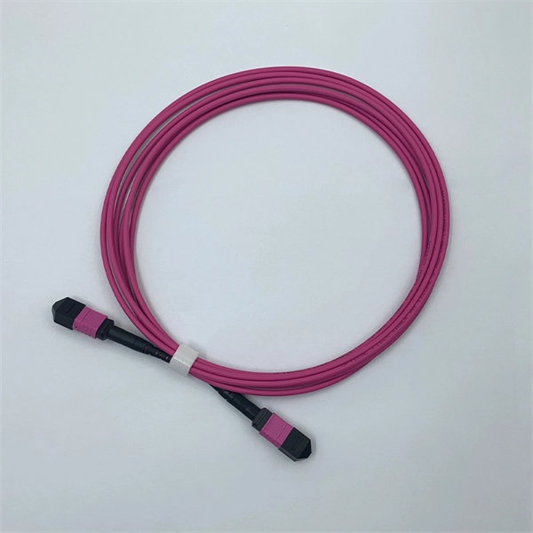
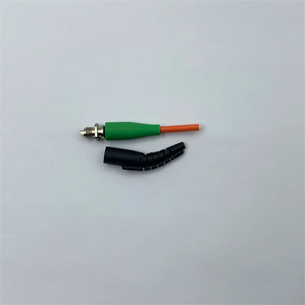
A multimode APC (Angled Physical Contact) connector is a fiber optic connector designed for high-performance optical signal transmission. Its key feature is the 8° angled polish on the connector's end face. SN®-MT They support both single-mode (SM) and multimode (MM) fibers and are widely used in space-constrained environments requiring high. The QSFP-100G modules are our latest generation of 100G transceiver modules solution based on a QSFP form factor. (See Figure 1) Figure 1. ● Hot-swappable input/output device that plugs into a 100G Gigabit Ethernet Cisco QSFP port. Similar to standard APC connectors, this design effectively reduces back reflection by. Corning manufactures a full line of high-performance APC (angle polish connector) fiber connectors and adapters. Corning 8-degree APC connectors are fully intermateable with standard NTT APC products and deliver long-term stability under a range of applications and conditions. Each type varies by shape, polish (APC, PC, or UPC), and return loss performance, which affect PC, UPC, and APC Polish Styles: What's the.
[PDF]
The connector mechanically orients the fiber cores, allowing light to pass and travel through the cable without interruption. Unlike electrical connectors, fiber optic connectors allow light signals instead of electrical signals, which requires the connector to be much more precise. The methods of fixing joints include fusion splicing method, V-groove method, capillary method, casing method, etc. The connector features a ferrule, the connector end piece that holds and secures the fiber and aligns it for light. Fiber optic connectors may look small, but they play a decisive role in the performance of today's high-speed networks. From data centers to telecom backbones, the choice of connector affects insertion loss, return loss, density, and even long-term reliability. The barrel provides the mechanical means by which the connector is held in place wit the mating half. A variety of methods are used to ensure the connector is held in place, ranging from screw fit, to. A fiber optic connectors, also known as an optical fiber connector, is a component that terminates the end of a fiber optic cable, enabling quicker connections and disconnections than fiber splicing.
[PDF]
Fiber optic "cable" refers to the complete assembly of fibers, other internal parts like buffer tubes, ripcords, stiffeners, strength members all included inside an outer protective covering called the jacket. Cable provides protection for the optical fiber or fibers within it appropriate for the environment in which it is installed. You will also learn how different aspects of the product can affect budget and design. ■ The Five Key Parts of a Fiber Optic Cable A fiber optic cable. A fiber optic cable consists of five basic components: the core, the cladding, the coating, the strengthening fibers, and the cable jacket. When searching for a fiber optic cable, we need to pay attention not only to the connectors, such as SC to ST fiber cable, LC to SC fiber patch cable, or SC to. A TOSLINK optical fiber cable with a clear jacket. These cables are used mainly for digital audio connections between devices. This advanced cabling solution allows fast, secure data transfer and telecom over long distances. Understanding the components within a fiber optic cable enables. While fiber optic cable itself is cheaper than an equivalent length of copper cable, fiber optic cable connectors and the equipment needed to install them have typically been more expensive than their copper counterparts.
[PDF]
In this paper, a thermally tuned silicon-based three-channel reconfigurable multimode interference (MMI) optical power splitter with four optimized thermal isolations is proposed. Specific and flexible reconfig-urable functions (1, , and MMI splitters) can be achieved by. Abstract: We demonstrate integrated photonic circuits for quantum devices using sputtered polycrystalline aluminum nitride (AlN) on insulator. 56(1), 017106 (2017), doi: 10. The two most common types of splitters offered are polarizing beam splitters and polarization maintaining beam splitters. Their operating principles are as follows: Polarization Maintaining. optical transimission & integration needs of any system. MEISU specializes in precise custom fiber array sub-assemblies and PM fiber optical components and assemblies for different areas like integrated optics, sensoring, healthcare, spectroscopy, etc., 50/50 FBS, can be used as the frequency-mode Hadamard gate for frequency-encoded photonic qubits. Quantum cryptography is the key point of quantum communication. In classical cryptography classical bits are used but in quantum cryptography quantum bits (qubit) are used. Quantum communication sends the information through some channels such that, optical fibre, satellite etc.
[PDF]
Frequent status changes from up to down or vice versa in the ports logged by the switch port syslog indicates a port flap. On a big industrial plant we've replaced an old HP switch with a brand new couple of C2960x switches in stack configuration and ever since then, every 6/8 hours or so, the two fiber optics links of switch #2 go down at once. These are connected to a ring of 3 similar other access switches, that. EX4650 2-switch virtual chassis, running version 19. 2, optic p/n 740-031981 (SFP+-10G-LR) is plugged into port xe-0/0/10 and connected to an ISP via single mode fiber. Nothing special is configured on the port, it is running at 10G speed, show interfaces diagnostics optics shows that it's. This article describes steps to diagnose the Continuous port flapping on a FortiSwitch. Verify Cable Connection: Ensure the cable is properly connected between the switch port and the end device. Run the command below on FortiSwitch multiple times and check the. Real head scratcher this morning that I'm hoping someone can help me with! The port on our core switch (HP A5500) that our Smoothwall box is connected to keeps going up and down. Port flapping, also known as link flapping, causes a switch port's state to fluctuate between up and down within concise periods of time. This instability caused by flapping ports affects network connectivity. Port flapping is a common network issue that can disrupt communication between devices and degrade overall network performance.
[PDF]
This Technical Brochure describes the induction phenomena (inductive, capacitive and conductive) that can lead to presence of voltage and currents on disconnected cable systems. The optical fiber composite overhead ground wire (OPGW) has been widely used in power transmission lines. Methods of calculation to evaluate those values and touch voltages are detailed and analysed, associated with various. working on cables u al, photocopying, recording or otherwise, without the prior written or use by members of the Energy Networks Association to take account of the conditions which apply to them. Advice should. Literature review: An in-depth literature review covering the modelling and calculations of the conditions relating to faults caused by interactions between fibre optic cables and power cores in submarine cables. Examples of electrically conductive installations where induced voltage may occur could be: • Overhead lines or cables out of opera- tion •.
[PDF]
The system in this example contains the following elements: 1. 2 Pseudo-random Bit Stream (PRBS) block 2. 2 NRZ Pulse Generator (NRZ) 3. 1 CW Laser (CWL) 4. 3 1x2 Fork (FORK) 5. 2 Electrical Not Gate (N.
[PDF]
In this Cisco Tech Talk, learn how to view the optical module status on a Cisco switch using the Command Line Interface (CLI). This video demonstrates how to access the optical module status, check for any issues, and monitor the health of your network's optical components. Learn. When optical modules operate on a switch, it is usually necessary to read the module's internal information to understand its working status—such as connection status and real-time metrics like optical power and temperature. Additionally, identifying module information helps detect coding. This chapter describes how to configure the Optical Amplifier Module and Protection Switching Module (PSM). When you plan to replace a configured optical module with a different type of optical module, you must clear the configurations of the old module before you install the new module. By checking module health, compatibility, and digital diagnostics, you can quickly confirm correct installation, detect optical problems, and maintain accurate hardware. Small Form-factor Pluggable modules (SFP module) are the workhorses of modern network connectivity, enabling flexible fiber optic or copper links between switches, routers, firewalls, and servers. Whether you're upgrading bandwidth, replacing a faulty unit, or reconfiguring your topology, knowing.
[PDF]
This paper aims to study the design, simulation, and optimization of low-loss Y-branch passive optical splitters up to 64 output ports for telecommunication applications. For a waveguide channel profile, the standard material silica-on-silicon is used. Two important technologies for optical layer monitoring are Optical Performance Monitoring (OPM) and Optical Power Detection (OPD). Although they aim to maintain network health, they differ significantly in scope, technique, and deployment. This article delves into these differences, equipping. Optical Performance Monitoring (OPM) is considered a necessity over an optical network to enable sensibility of traffic line status and attain outstanding Quality-of-Service (QoS). The Y-splitters are designed and simulated at. Passive optical networks (PONs) are the network architecture of choice for residential fiber deployments. A PON is designed specifically to be cost-effective for delivering high data-rates to large customer populations. signals and various components of OPM functionalities are indispensable robust network operation and plays a key role flexibility and improve overall. Optical performance monitoring (OPM) is used for managing high capacity dense wavelength-division multiplexing (DWDM) optical transmission and switching systems in Next Generation Networks (NGN). OPM involves assessing the quality of data channel by measuring its optical characteristics without.
[PDF]
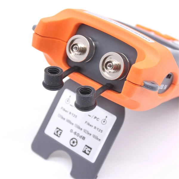
Calibration & Repair services in Ireland. 5 day turn around with competitive pricing! View full electrical test and measurement equipment list here. is an independent calibration laboratory focused on meeting the total quality requirements of industry. Proper calibration of today's sophisticated test and measurement equipment is essential for preserving measurement accuracy, complying with international standards. Parameters covered include; Temperature, Humidity, Dewpoint, Various Gases, Pressure, Electrical, Weights & Scales, Analytical and some Specialist calibrations. Calibration is performed using the very latest Calibration Equipment/Standards & Calibration/Asset Management Software. Fast Efficient. PTM Calibration offers a wide range of services that complement our core business. We aim to be your one stop shop for all your calibration, test & measurement needs. From major blue chip companies & medium enterprises to small companies and sole traders. Including: aerospace, pharmaceuticals. OptiCal Sciences are an authorised service centre with service, repair and calibration experience and procedures for an extensive variety of models from a wide range of manufacturers.
[PDF]
The SFP optical module is a standardized, modular assembly designed to be quickly installed or removed from a device's port without requiring the device to be powered down. This key feature—being hot-pluggable —is essential for simplifying network maintenance and minimizing downtime. SFP (Small Form-factor Pluggable) is a compact, hot-pluggable network interface module used to connect network devices (switches, routers, firewalls) to fiber optic or copper cables. It converts electrical signals into optical (or copper) signals and vice versa. An SFP transceiver acts as a compact, hot-swappable optical transceiver that. An SFP switch uses Small Form-Factor Pluggable (SFP) modules to form a network switch for high-speed connectivity between devices. These interchangeable modules support various media types, including copper or fiber-optic cables, providing flexible networking options based on specific requirements.
[PDF]
Optical trap or "tweezers" is a device used to apply piconewton sized forces and make precise measurements on a scale of roughly one micron. It can be created by applying a precisely focused laser onto a dielectric material. Thorlabs' OTKB (/M) Modular Optical Tweezers provide users with a tool for trapping and manipulating microscopic-sized objects. These laser-based tweezers, or traps, have been employed in numerous biological experiments. Biological applications for optical tweezers include trapping viruses and. Our advanced optical trap generator based on ultra-fast AOD technology. Versatile and flexible optical trap manipulation designed for biological samples. Learn to calibrate the 20. Use calibration information to observe the rotation of E. coli bacteria, and determine the forces required to stop this rotation. Based on their design, Thorlabs has collaborated with the aforementioned authors to design an OTKB optical trapping kit that includes all necessary components and provides the same capabilities. Enclosed into a high-quality aluminum box and assembled onto the. Torr Scientific offers a range of magneto-optical traps (MOT) (also known as atom trap chambers) used as part of ultra-cold vacuum systems, to capture atoms for testing purposes. This is a chamber module, formed of low-magnetic permeability materials for use at ultra-low temperatures nearing.
[PDF]
Multi-mode optical modules can only be used for short-distance transmission (SR) due to serious inter-mode dispersion; while single-mode optical modules are mostly used for long-distance transmission such as LR, ER, and ZR. Whether you are in need of single-mode optical modules for lines that require high transmission rates and long distances, or multi-mode optical modules for short-distance transmission scenarios with numerous network nodes and connectors, you can find the optical modules you desire at the LINK-PP. Single-mode fiber uses a 9/125 µm core/cladding structure that supports only one propagation mode, which minimizes modal dispersion and allows signals to travel tens of kilometers with low attenuation. Multimode fibers have larger cores (typically 50/125 µm or 62. Under normal circumstances, the transmission distance of less than 2km is. An optical fiber is a cylindrical dielectric waveguide composed of a central core surrounded by cladding with a slightly lower refractive index. This carefully engineered index contrast confines light within the core through total internal reflection, enabling optical signals to travel with. If your network requires long-distance transmission (over 550 meters), a single-mode optical module is the best choice. For shorter distances, multi-mode modules are more appropriate. Single-mode modules offer higher bandwidth capabilities, making them suitable for high-speed data transmission.
[PDF]
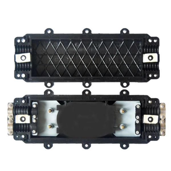
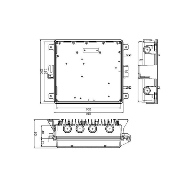
OPGW cable joint box installation involves several key stages: selecting the appropriate location, preparing both the cable and the joint box, splicing fibers, and sealing the joint box properly. Adhering to these steps ensures optimal performance and longevity of the telecommunications system. Optical fiber junction boxes are essential components in outdoor optical fiber cable installations. In this article, we will discuss the necessary steps and best practices. The Indoor/Outdoor Splice Box is a wall-mounted, indoor/outdoor fiber splice enclosure for centralized splice-only applications. These boxes are well suited as optical cable splice collection points for MDU (Multi-Dwelling Unit) residential fiber network applications, MTU (Multi-Tenant Unit). The installation of an optical cable junction box is crucial in ensuring the integrity and performance of optical networks. As we enter 2024, adhering to best practices not only enhances system reliability but also mitigates potential issues that can affect customer experiences. Installing a fiber optic splice closure efficiently and effectively requires attention to detail and. AFL's SB01 splice enclosure provides protection from all types of elements. From weather to bullets, the iron and steel construction requires no additional protective covering. Furnished with four plugged cable ports (2 aluminum and 2 plastic) for either All-Dielectric Self-Supporting (ADSS) or.
[PDF]
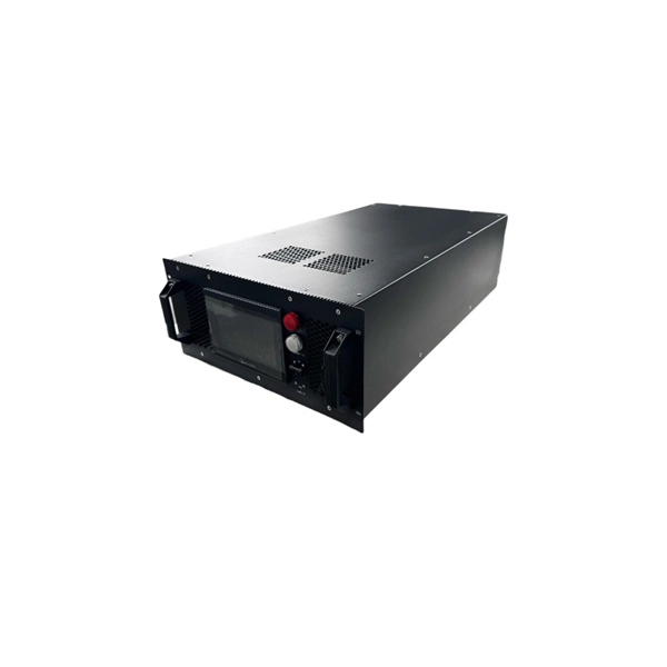
Lasers, modulators, and photodiodes form the core architecture of optical transceivers, enabling light-speed communication across global networks. Lasers generate the optical carrier. Modulators encode digital information. An optical transmitter is a crucial device used in fiber optic communication systems. Its primary function is to convert electrical signals into optical signals It involves modulating electronic system data and transforming it into light pulses using a laser or LED, and sending the pulses through. The optical transmitter and the optical receiver are the core components that enable this process, forming the electronic-to-optical and optical-to-electronic gateways necessary for modern, high-capacity data transmission. It takes data from an electronic system, uses a laser or LED to modulate that data into pulses of light, and then sends those pulses down the fiber. Together, lasers, modulators, and. At the core of a fiber optic system is the optical fiber – a flexible, transparent strand of glass, thinner than a human hair. Optical fiber is formed by drawing glass or plastic to a diameter slightly thicker than that of a. What are the main elements of an optical transmitter? Data decoder/demodulator, electrical interface, detector, optical interface.
[PDF]