This report provides a comprehensive analysis of the optical active device market, encompassing various segmentations: By Type: Lasers, modulators, photodetectors, amplifiers, etc., each with their own specific performance characteristics and applications. The global Active Optical Devices market was valued at US$ million in 2023 and is anticipated to reach US$ million by 2030, witnessing a CAGR of % during the forecast period 2024-2030. The Global Info Research report includes an overview of the. Optical Active Device by Application (IT Industry, Telecom, Other), by Types (Optical Transceiver Module, Light Detector, Light Modulator, Other), by North America (United States, Canada, Mexico), by South America (Brazil, Argentina, Rest of South America), by Europe (United Kingdom, Germany. The Optical Active Device Market Size was valued at 36. 3 USD Billion in 2024. The Optical Active Device Market is expected to grow from 38. North American market for Active Optical Devices is estimated to increase from $ million in 2024. Abstract—A wireline receiver consisting of a linear equalizer, a decision-feedback equalizer (DFE), a clock and data recov-ery (CDR) circuit, and a demultiplexer (DMUX) employs new circuit and architecture techniques that afford substantial power savings. Realized in 28-nm technology, the 56-Gb/s.
[PDF]
Learn how to extend GDB with optical signal breakpoints for efficient photonics chip debugging and testing with practical implementation steps. Debugging photonics chips requires specialized tools that can monitor and analyze optical signals alongside electronic ones. Legal status (The legal status is an assumption and is not a legal conclusion. Google has not performed a legal analysis and makes no representation as to the accuracy of the status listed. ) Current Assignee (The listed assignees may be inaccurate. These modules leverage advanced signal processing, modulation, and high-speed interfaces to provide high bandwidth, low latency, and reliable performance. Standard debugging tools like. modules used with NADDOD switches, for reference by technicians and users. For any questions, please contact NADDOD. When testing PRBS, there are 3 test nodes: MAC ----> PHY. In view of this, the embodiments of the present invention expect to provide an optical module commissioning device, commissioning method, and electronic equipment to solve the time-consuming technical problem of manually commissioning a DSFP optical module through a commissioning device in. Optical detection chips serve as essential components in intelligent optical computing systems, demonstrating crucial significance. These chips exhibit high sensitivity and broad wavelength response ranges, enabling precise optical signal reception and conversion while providing reliable data input.
[PDF]
Choosing between single-mode and multi-mode optical fiber shapes the performance ceiling of every high-bandwidth industrial sensing network. This guide maps the key technical distinctions, applicable standards, and the most productive research directions for. Optical fibers are among the most transformative technologies in modern photonics, quietly enabling the global internet, precision sensing, minimally invasive medicine, and high-power industrial laser systems. The. Discover ROI-boosting fiber choices: Single Mode vs Multimode Fiber. Get the right speed & savings for your network—download our guide for free today! Understanding the physics behind Single Mode vs Multi‑Mode Fiber is essential for selecting the right conduit for any optical network. Single‑mode. Choosing single mode or multi-mode installation is unquestionably one of the most crucial decisions. Understanding the distinctions between these two kinds of fiber glass are crucial since it will have a significant impact on your network's range, bandwidth, and spending. Single mode means the. Optical fiber cable transmits data as light at speeds exceeding 100 Gbps, far surpassing the 10 Gbps capabilities of legacy Cat 6A copper cable. Additionally, optical fibers support significantly higher bandwidths over greater distances without signal degradation. While both use light to transmit data, they differ fundamentally in core structure and how light travels.
[PDF]
Polarization dependent loss (PDL) is a measure of the peak-to-peak difference in transmission of an optical component or system across all possible states of polarization. It is the ratio of the maximum and minimum transmission of an optical device with respect to all polarization. The determination of polarization dependent loss has become a stan-dard measurement when character-izing passive optical components. In optical networks, where polarization is not constrained and changes randomly, the PDL of components can accumulate in an uncontrolled manner. This effect can. arch, and 3) Matrix measurements using Mueller or Jones matrices. Each method has its own advantages and disadvantages in terms of measuremen ice under test (DUT) while the DUT's output power is monitored. The built-in motor con-trolled PDLE units have low insertion loss, low backreflection, low PMD and flat wavelength response. This. This is the authors' extended version of an article that has been published in Proc. 21th ITG-Symposium on Photonic Networks, ISBN 978-3-8007-5424-3. The final version of record is available at https://www. de/buecher/455423/itg-fb-294-photonische-netze. Abstract—A number. Abstract—State-of-the-art polarimeter calibration is reviewed. Producing many quasi-random polarization states and moving/bending a fiber without changing power allows finding a polarimeter calibration where the degree-of-polarization reaches unity and parasitic polarization-dependent loss is.
[PDF]
Co-Packaged Optics (CPO) is an emerging technology that integrates optical engines directly with electronic switching chips to enable higher bandwidth, lower power consumption, and improved signal integrity in next-generation data centers and high-performance computing systems. As applications like AI and machine learning become more prevalent, demanding higher bandwidth data processing capabilities, CPO technology provides a scalable solution that can grow with these needs. Corning is taking part in the co-packaged optics revolution with our innovative fiber and optical. Co-packaged optics (CPO) is a disruptive approach to increasing the interconnecting bandwidth density and energy eficiency by dramatically shortening the electrical link length through advanced packaging and co-optimization of electronics and photonics. CPO is widely regarded as a promising. The relentless surge of artificial intelligence, hyperscale computing, and next-generation networks is exposing the limitations of traditional pluggable optical transceivers. Electrical signal integrity challenges, escalating power consumption, and physical density constraints at speeds exceeding. Traditional optical interconnects have long been used in networking applications, but silicon photonics takes the technology a step further by integrating optics directly into semiconductor chips (FIGURE 1). But after nearly a decade of existence, where does this next-generation optical.
[PDF]
An optical power meter is an electronic device that measures the power of an optical signal. It helps engineers verify the performance of optical fiber systems, ensuring that the signal strength meets requirements, and is an essential tool for communication network maintenance and. An optical power meter (OPM) is a device used to measure the power in an optical signal. Other general purpose light power measuring devices are usually called radiometers, photometers, laser power meters (can be. An optical power meter (OPM) measures the power levels of light signals in devices that transmit data or power using light. The term "optical power meter" may sound generic, but in popular usage, it specifically implies a fiber optic power meter. For light power measurements outside the field of. Optical Power Meters (OPMs) are crucial instruments in the field of optical sensors and fiber optic communications. It provides an expert-curated supplier directory, buyer-focused technical background information, and structured selection criteria to support professional procurement decisions. It measures optical power directly, and it is also used in loss testing when paired with a stable light source.
[PDF]
Frequent status changes from up to down or vice versa in the ports logged by the switch port syslog indicates a port flap. On a big industrial plant we've replaced an old HP switch with a brand new couple of C2960x switches in stack configuration and ever since then, every 6/8 hours or so, the two fiber optics links of switch #2 go down at once. These are connected to a ring of 3 similar other access switches, that. EX4650 2-switch virtual chassis, running version 19. 2, optic p/n 740-031981 (SFP+-10G-LR) is plugged into port xe-0/0/10 and connected to an ISP via single mode fiber. Nothing special is configured on the port, it is running at 10G speed, show interfaces diagnostics optics shows that it's. This article describes steps to diagnose the Continuous port flapping on a FortiSwitch. Verify Cable Connection: Ensure the cable is properly connected between the switch port and the end device. Run the command below on FortiSwitch multiple times and check the. Real head scratcher this morning that I'm hoping someone can help me with! The port on our core switch (HP A5500) that our Smoothwall box is connected to keeps going up and down. Port flapping, also known as link flapping, causes a switch port's state to fluctuate between up and down within concise periods of time. This instability caused by flapping ports affects network connectivity. Port flapping is a common network issue that can disrupt communication between devices and degrade overall network performance.
[PDF]
Fiber optic "cable" refers to the complete assembly of fibers, other internal parts like buffer tubes, ripcords, stiffeners, strength members all included inside an outer protective covering called the jacket. Cable provides protection for the optical fiber or fibers within it appropriate for the environment in which it is installed. You will also learn how different aspects of the product can affect budget and design. ■ The Five Key Parts of a Fiber Optic Cable A fiber optic cable. A fiber optic cable consists of five basic components: the core, the cladding, the coating, the strengthening fibers, and the cable jacket. When searching for a fiber optic cable, we need to pay attention not only to the connectors, such as SC to ST fiber cable, LC to SC fiber patch cable, or SC to. A TOSLINK optical fiber cable with a clear jacket. These cables are used mainly for digital audio connections between devices. This advanced cabling solution allows fast, secure data transfer and telecom over long distances. Understanding the components within a fiber optic cable enables. While fiber optic cable itself is cheaper than an equivalent length of copper cable, fiber optic cable connectors and the equipment needed to install them have typically been more expensive than their copper counterparts.
[PDF]
The CFP standard defines a pluggable optical transceiver form factor capable of supporting 40G and 100G Ethernet, OTN (Optical Transport Network), and SONET/SDH protocols. The acronym "CFP" represents the Roman numeral "C" (100), aligning it with 100 Gigabit Ethernet. Originally introduced as the first standardized pluggable solution for 100 Gigabit Ethernet, CFP (C Form-factor Pluggable) modules were engineered to support high-bandwidth, long-distance transmission using multiple optical lanes. Their robust design made them ideal for carrier-grade networks, DWDM. The C form-factor pluggable (CFP, 100G form factor pluggable, where C is Latin: centum "hundred") is a multi-source agreement to produce a common form-factor for the transmission of high-speed digital signals. Developed collaboratively. The CFP optical transceiver module is a standardized, hot-swappable optical transceiver used for high-speed data transmission in telecommunications and data center networks. CFP transceivers are defined by CFP MSA to enable 40 Gb/s, 100 Gb/s and 400 Gb/s applications. It features a new concept known as. This article breaks down the key differences between CFP, CFP2, CFP4, and CFP8 optical transceivers commonly used in fiber optic networks. Figure 1: Dimensions of CFP, CFP2, CFP4, and CFP8 The table below summarizes the specifications of each form factor: 24 W (Max. ) In essence, the progression.
[PDF]
This paper aims to study the design, simulation, and optimization of low-loss Y-branch passive optical splitters up to 64 output ports for telecommunication applications. For a waveguide channel profile, the standard material silica-on-silicon is used. Two important technologies for optical layer monitoring are Optical Performance Monitoring (OPM) and Optical Power Detection (OPD). Although they aim to maintain network health, they differ significantly in scope, technique, and deployment. This article delves into these differences, equipping. Optical Performance Monitoring (OPM) is considered a necessity over an optical network to enable sensibility of traffic line status and attain outstanding Quality-of-Service (QoS). The Y-splitters are designed and simulated at. Passive optical networks (PONs) are the network architecture of choice for residential fiber deployments. A PON is designed specifically to be cost-effective for delivering high data-rates to large customer populations. signals and various components of OPM functionalities are indispensable robust network operation and plays a key role flexibility and improve overall. Optical performance monitoring (OPM) is used for managing high capacity dense wavelength-division multiplexing (DWDM) optical transmission and switching systems in Next Generation Networks (NGN). OPM involves assessing the quality of data channel by measuring its optical characteristics without.
[PDF]
This Technical Brochure describes the induction phenomena (inductive, capacitive and conductive) that can lead to presence of voltage and currents on disconnected cable systems. The optical fiber composite overhead ground wire (OPGW) has been widely used in power transmission lines. Methods of calculation to evaluate those values and touch voltages are detailed and analysed, associated with various. working on cables u al, photocopying, recording or otherwise, without the prior written or use by members of the Energy Networks Association to take account of the conditions which apply to them. Advice should. Literature review: An in-depth literature review covering the modelling and calculations of the conditions relating to faults caused by interactions between fibre optic cables and power cores in submarine cables. Examples of electrically conductive installations where induced voltage may occur could be: • Overhead lines or cables out of opera- tion •.
[PDF]
In this Cisco Tech Talk, learn how to view the optical module status on a Cisco switch using the Command Line Interface (CLI). This video demonstrates how to access the optical module status, check for any issues, and monitor the health of your network's optical components. Learn. When optical modules operate on a switch, it is usually necessary to read the module's internal information to understand its working status—such as connection status and real-time metrics like optical power and temperature. Additionally, identifying module information helps detect coding. This chapter describes how to configure the Optical Amplifier Module and Protection Switching Module (PSM). When you plan to replace a configured optical module with a different type of optical module, you must clear the configurations of the old module before you install the new module. By checking module health, compatibility, and digital diagnostics, you can quickly confirm correct installation, detect optical problems, and maintain accurate hardware. Small Form-factor Pluggable modules (SFP module) are the workhorses of modern network connectivity, enabling flexible fiber optic or copper links between switches, routers, firewalls, and servers. Whether you're upgrading bandwidth, replacing a faulty unit, or reconfiguring your topology, knowing.
[PDF]
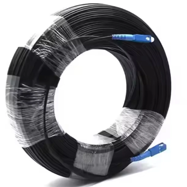
A 4-core fiber optic cable is a type of cable that contains four individual optical fibers within a single protective jacket. These fibers are used to transmit data as light signals, offering high-speed data transfer capabilities over long distances with minimal loss. This guide covers everything you need to know about 4 core fiber, including its internal structure, TIA standard color coding, and how to choose the right type. They are used to connect final user to FTTH or GPON line. Jera is a direct manufacturer who supply a wide range product for. This cable can be used for LAN and WAN backbones, telecom access lines, fibre to business and fibre to the building or the homme connections. It is equally suited for installation in ducts and on trays. This cable features a 0. 15mm corrugated steel armour which makes it rodent proof. OM3 and higher. A TOSLINK optical fiber cable with a clear jacket. What is a 4 Core Optical Cable? A 4 Core Optical Cable is a fiber optic cable that contains four individual optical fibers within a single. Unlike copper wires, which are limited by lower data transmission speeds, shorter transmission distances, and higher susceptibility to electromagnetic interference, fiber optic cables offer unparalleled performance and can cover much greater distances without bumping up against signal degradation.
[PDF]
Abstract: Detecting partial discharges in cable joints is critical for timely defect identification and reliable transmission system operation. The electric field distribution of the optical fiber-implanted cable joint was simulated, followed by electrical performance tests, demonstrating that optical fiber implantation had a negligible effect on the electrical properties of the cable joint. A platform utilizing Mach–Zehnder–Sagnac. The results show that the average sensitivity of the sensor in the 10 kHz–80 kHz range is 71. 0 dB higher than that of the piezoelectric transducer, with a maximum signal-to-noise ratio of 65. To improve the long-term reliability and sensitivity of the sensing system, a novel method for cable joint monitoring based on implanting optical fibers. However, there is an industry gap in the literature about the highly sensitive fiber optic-based PD solution based on the acoustic emission principle. This paper aims to fill such an industry gap. In this paper, the fiber optic-based PD sensing (OptiFender) technology is applied to monitor the PD.
[PDF]
Total number of cores = Number of branches × Number of cores per branch If there are no branches, the number of branches equals one. For example, an MTP®-8 trunk cable with four branches and eight cores per branch has a total of 32 cores (4 × 8 = 32). For example, if you have three optical fiber access switches, you need to have three cores. (actually use a four core optical cable) This is because apart from one-core optical fiber, there are basically no optical cables with an odd number of cores, such as three-core, five-core, etc. It is worth. Fiber cores are the heart of fiber optic cables, transmitting light signals that carry data. Made from either high-quality glass or plastic, the core plays a critical role in determining the cable's performance. The total number of cores for a 1pc fiber patch cable is calculated as the number of. One key factor is the number of cores, which impacts how much data you can transmit. Single-mode: A. Common fiber cores include 1 core, 2 cores, 6 cores, 8 cores, etc., and there are many types. This article will focus on the number of fiber cores, introducing their respective characteristics and usage scenarios. Of course, this is a general situation, and it can be considered as follows: 1.
[PDF]