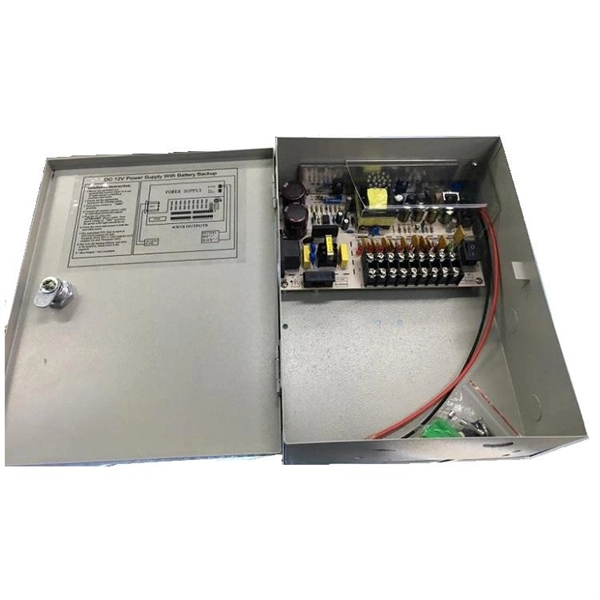
This video illustrates the step-by-step connection from the energy meter (KWH Meter) to the main Double-Pole MCB, the Neutral Link terminal block, and finally to the four individual Single-Pole Miniature Circuit Breakers (MCBs) for distribution to different circuits. In this guide, we will break down the key elements involved in connecting the main power supply to your home, providing a clear path for a successful setup. We will focus on the critical parts of the system, from basic components to step-by-step assembly procedures. Whether you are looking to. Always begin with disconnecting the main supply before accessing any enclosure containing distribution components. This prevents arc faults and ensures safety when modifying or inspecting current paths. Inside the service housing, line conductors from the utility feed typically enter through the. When it comes to electrical wiring, the connection between the meter and breaker box is crucial. This connection ensures that electricity is properly distributed throughout the building, allowing appliances, lights, and other devices to function. It shows the hot wire entering the meter lugs, the neutral wire connecting to the neutral bus bar, and the essential ground wire linkage to ensure system safety. Watch a simple and clear demonstration of how to wire a basic residential electrical setup. The diagram provides a clear and concise overview of how the meter is connected to the electrical.
[PDF]
Slide the electric meter into its slot in the box. Make sure it's seated properly and lines up with the mounting mechanism. Once aligned, lock or secure it into place to prevent movement or tampering. This step is especially important if your meter is installed outdoors. energy meter connection with distribution box How to Connect an Energy Meter to Your Distribution Box Easily Steps to Properly Connect Your Energy Meter to a Distribution Box. Inside the service housing, line conductors from the utility feed typically enter through the. An electric meter box wiring diagram is a visual representation of the electrical connections and circuits involved in connecting an electric meter to the rest of the electrical system in a building. The diagram provides a clear and concise overview of how the meter is connected to the electrical. The process of connecting a meter socket to a main breaker panel involves the installation of service entrance conductors, which carry the full electrical load and voltage from the utility supply into a building. Following is the figure and the steps that you need to follow while wiring a meter socket: Figure 1: Meter Socket Wiring. When it comes to the electrical system in a building, one of the crucial components is the wire that connects the meter to the breaker box. It plays a vital role in.
[PDF]
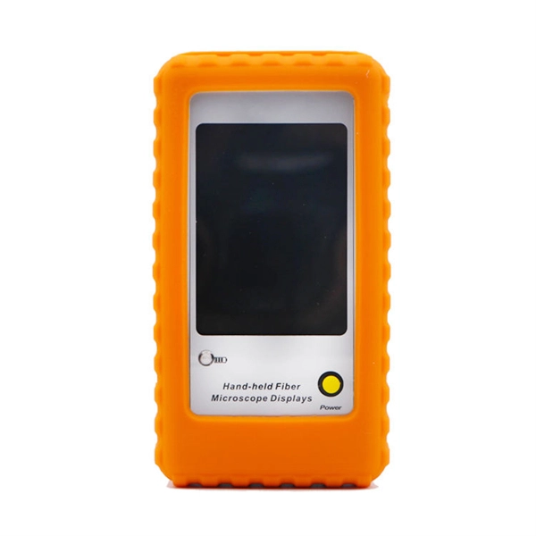
An optical power meter (OPM) works by converting light energy into electrical energy using a photodiode sensor. When light from a fiber optic cable hits the sensor, it generates a small electrical current related to the light's strength. Optical power meters are a key element in the optimization and maintenance of such optical networks and of their components. In this article, learn: What is an optical power meter? An optical power meter (OPM) measures the power levels of light signals in devices that transmit data or power using. An optical power meter (OPM) is a device used to measure the power in an optical signal. The term usually refers to a device for testing average power in fiber optic systems. It measures the optical power transmitted through a fiber, helping to verify if the light signal is strong enough for communication. Beginners may find it complex, but understanding its function makes it. This article provides a comprehensive overview of optical power meters, instruments used to measure the power of light beams. It details the main components, including sensor heads and display units, and explains the two primary sensor technologies: robust thermal sensors for high powers and. A fiber-optic power meter is a quantitative measurement instrument, not a diagnostic tool by itself.
[PDF]
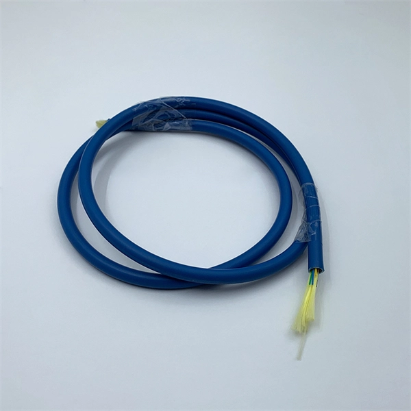
Typical rates range from $0. 00 per ft depending on terrain, access, and required precision for termination. Basic — 1,000 ft single-mode run indoors with minimal termination: Cable $0. 00/ft, Permits $150, Accessories $100. Total ≈ $2,650–$3,100. 🔥Buy Fiber Cables products online from DanounTech the best tech store📱 in Lebanon🇱🇧 | find low prices everyday, and enjoy fast delivery🚚. DanounTech | LEBANON. Fiber optic solutions (drawers, panels, connectors. ) | Fibre optic cables | !. 50-meter, 2-core single-mode fiber optic cable with APC (Angled Physical Contact) connectors, providing low-loss, low-reflection performance for high-speed data transmission. Ideal for FTTH, telecom, and network infrastructure requiring reliable duplex connectivity. Each cable features advanced fiber optic technology to deliver superior performance, low latency, and high bandwidth. Anixter is your source for Indoor/Outdoor Fiber Optic Cable products. olx Lebanon offers online local classified ads for Fiber Optic. Post your classified ad in various categories like mobiles, tablets, cars, bikes, laptops, electronics, birds, houses, furniture, clothes, dresses for sale in Lebanon.
[PDF]
In this video, we'll show you how to connect an energy meter to a distribution board (DB) safely and efficiently. energy meter connection with distribution box How to Connect an Energy Meter to Your Distribution Box Easily Steps to Properly Connect Your Energy Meter to a Distribution Box. Site/existing equip info - SFH (1 story, no basement, just crawlspace) w/ attached garage. 200A main service (Leviton panel). Covers wiring, placement, standards, and expert tips for a compliant setup. A distribution box is the heart of any electrical system. It takes the incoming power and safely distributes it to different circuits throughout your building. I am going to start digging a trench to run underground cable from a service pole breaker box to a well house; the distance is 60 feet. The breaker is a 240 V 2-pole 20-20 which will run to the well house water pump pressure switch. The present UF 2-10 AVG with ground cable runs two inches under. An electric meter box wiring diagram is a visual representation of the electrical connections and circuits involved in connecting an electric meter to the rest of the electrical system in a building. The diagram provides a clear and concise overview of how the meter is connected to the electrical. Limited the meter location from pad mount transformer for PSO. APCo and TX do not allow unistrut for installations. 7/2020 Revised Figure 15. Added wording for consistency with Section 8 of document.
[PDF]
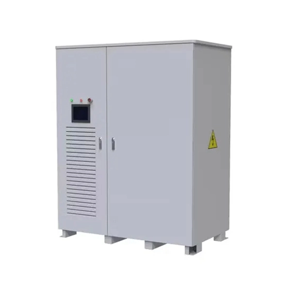
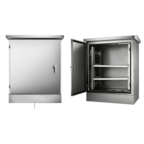
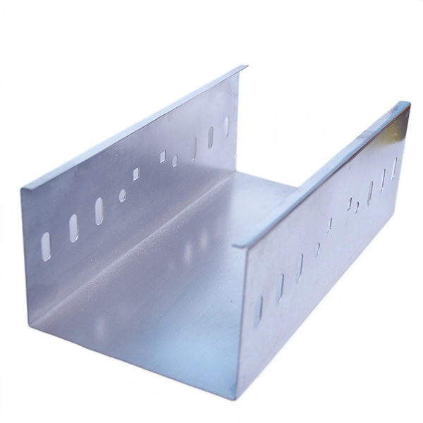
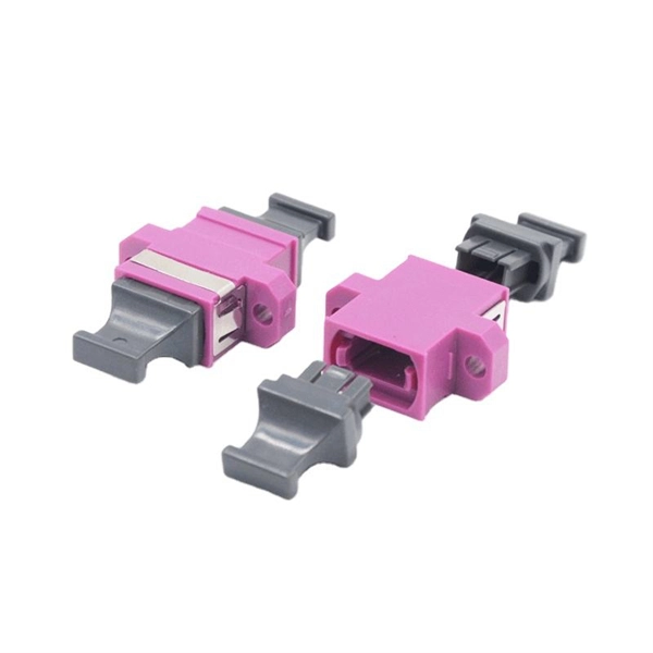
Engineered for FTTH network systems, this all-in-one outdoor optical distribution box seamlessly integrates splicing, splitting, distribution, and cable storage within a single, weatherproof enclosure. The 8 core optical branching box is produced and developed by our company completely, and the product's performance in accordance with the industry standard requirements. It's mainly used in FTTX access system terminal link. The box made of high strength PC plastic alloy injection molding, which. Deploy a reliable and robust fiber access point with the JUNPU JP-I1-8OA outdoor fiber distribution box. Maximum capacity: 8 SC simplex, 8 LC duplex. The 8 port Fiber Distribution Box is sturdy in structure, lightweight in size, and easy to install. It can be installed on walls or utility poles, and its waterproof cover ensures maximum moisture protection, ensuring optimal performance in any weather. Price changes against quantity. OEM / ODM is available. Capacity Leading fiber optical box manufacturers & suppliers, provide a range of fiber optic box with different core numbers and support OEM ODM service. The 8-core outdoor fiber optic distribution box provided by OTRANS can effectively improve the stability and security of network transmission, and is widely used in various scenarios such as FTTH networks, CATV networks, local area networks, and telecommunications networks. The fully enclosed.
[PDF]
Drawing on IEC standards and industry research data, it outlines the coverage of mainstream outdoor fiber optic cable types, selection criteria, and best practices for installation, providing a systematic reference for outdoor fiber optic cable deployment. This document serves as a guide for outdoor fiber optic cable selection and installation for professionals in the telecommunications industry. Fiber optic cables for outdoor applications are engineered to withstand the more demanding conditions seen outside, from environmental extremes to mechanical forces. These are the outdoor fiber optic cables you see strung along telephone poles (aerial), installed inside an underground duct, or even. Outdoor fiber optic cables transport data and communications signals over long distances while enduring extreme environments. Whether you're linking buildings, running broadband in rural areas, or building 5G infrastructure, the right cable matters. It affects performance, maintenance, cost, and reliability. Our team will make sure the configuration is tailored to your needs and will provide a detailed quote. Email us using the Request a Quote below, or. hing, conduit and temp rature variations. The Outside Plant cable. These cables are thoroughly tested designed for installation in pathways that are subjected to wide product line offers 6 and 12 fibers per and verified to Telcordia GR 20 a loose tube cables and hybrid design o ts to specific.
[PDF]
Choosing Figure 8 fiber optic cable means investing in a solution that offers: 1. Cost savings on installation and maintenance. 2. Exceptional performance with high tensile strength. 3. Adaptability for single-m.
[PDF]
Provides accurate and cost-effective testing methods for the optoelectronic signal testingand anomaly simulation of high-speed optical transceiver modules. The OptoBERT™ OPB04X10 is the industry's most compact, cost-effective, easy-to-use 4-channel 10Gbps electrical bit-error-ratio tester (BERT). PBT3058 is a high-performance Bit Error Ratio Tester which can be used for physical layer characterization and consistency test of high-speed serial signal. 6TBASE/CEI-224G standards and also supports PCIe rate testing ranges through extended rate. Transmitter net measurement:. Our portable and stationary provers ensure accuracy and industry compliance for flow meters on a variety of in the field applications. Available in custom configurations and max flow rates, each prover is designed to eliminate the many prover problems of the past including our Unidirectional. In high-speed digital communication systems, even the smallest bit-level error can compromise performance, reduce efficiency, or lead to costly rework. That's why Physical Layer Tech offers precision-engineered Bit Error Rate Testers (BERTs) designed to verify data transmission accuracy and ensure. Whether you are looking for the smallest handheld 100G bit error rate tester in the world for your field job, or perhaps your needs take you into the lab, VIAVI has you covered with our accurate and easy-to-use BERT equipment for any use case. · Use control board and replaceable.
[PDF]
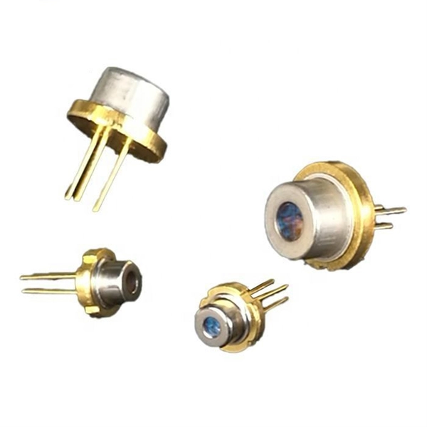
At the heart of every optical transceiver lie three essential components, often called the “Three Pillars” of optical communication: Laser — generates light. Modulator — encodes data onto the light. Photodiode — decodes light signals back into electrical form. As an essential component of optical fiber communication, optical modules are optoelectronic devices that facilitate the conversion between optical and electrical signals during the transmission process. Operating at the physical layer of the OSI model, optical modules are core devices in optical. An optical module usually consists of an optical transmitting device (TOSA, including a laser), an optical receiving device (ROSA, including a photodetector), functional circuits,main control circuit board (PCBA), housing and optical (electrical) interface and other components. Together, lasers, modulators, and. That is, metal medium communication represented by coaxial cables and network cables is gradually being replaced by optical fiber media. Composition of Optical Modules The optical module, known as Optical Transceiver in. This comprehensive guide breaks down the internal structure, core components (TOSA, ROSA, lasers), and operational mechanisms of SFP optical modules, enriched with technical insights and real-world applications. These modules typically consist of a transmitter, which converts electrical signals into a light signal, and a receiver, which converts the received signal back.
[PDF]
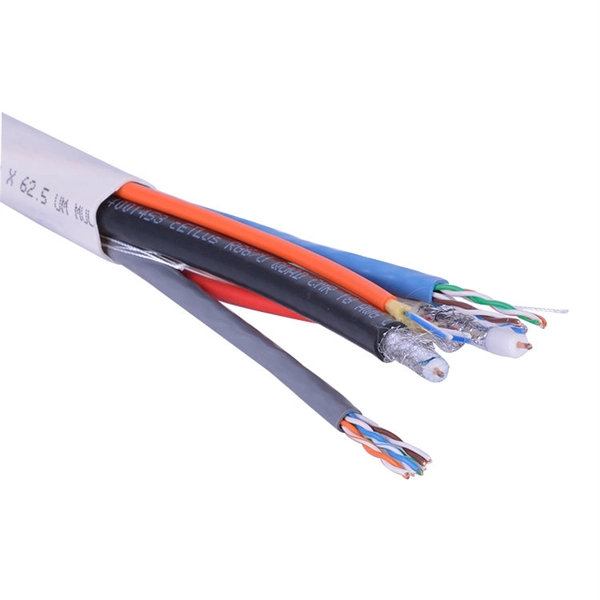
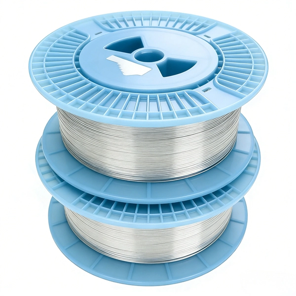
As shown in the figure below, the main cable consists of three conductor wires extending from the top of the motor flat lead extension to the wellhead banded to the production tubing. The ESP cable carries current (amperage) from the motor controller at the surface down to the motor. CAVALCADE™ ESP power cable meets the high-quality standards required for any oil and gas industry specification–even the most challenging unconventional applications–to deliver the electrical requirements of your ESP and to extend system run life. Get cable built with solid copper conductors. Typically, it is banded or clamped to the production tubing from below the wellhead to the ESP unit because it is not designed to support its own weight. It is a specially constructed three-phase power. Levare is one of few artificial lift equipment providers manufacturing the complete ESP system including power cable. The total facilities capacity is approximately 10,000 kilometers (over 6,200 miles) of power and motor lead extension (MLE) cables annually. It is a specially constructed three-phase power cable designed. When performing well interventions, the choice of a suitable cable is critical to ensure well control is maintained while deploying wireline through pressure control equipment (PCE). Depending on the well conditions, many considerations should be taken into account for choosing the best cable.
[PDF]
Instead of fusing one fiber at a time, mass fusion splicing can fuse up to all 12 fibers in one ribbon at once. Many of today's cables with high fiber count involve subunits of 12 fibers each that can be quickly ribbonized. Fiber optic joints or terminations are made two ways: 1) splices which create a permanent joint between the two fibers or 2) connectors that mate two fibers to create a temporary joint and/or connect the fiber to a piece of network gear. Either joining method must have three primary characteristics. Fiber optic splicing is the process of seamlessly joining two single Splicing has a lower optical loss and back-reflection than other terminations, making it the ideal choice for maintaining signal integrity and reliability in fiber optic networks. There are numerous use cases for fiber optic splicing. Through splicing, fiber optic technicians can extend the length of the fiber to make it long enough for use in a required cable run. As. To begin, the standard definition of splicing in optical fiber is joining two fiber optic cables together. The other, more common, method of joining fibers is called termination or connectorization. Splicing is most commonly used in the field but has application in cable assembly houses.
[PDF]
Square D by Schneider Electric offers a unique replacement kit designed to adapt to all brands, different use case scenarios and load type devices such as Load Centers and CSEDs. This kit consists of tw.
[PDF]
Optical splitters enable a signal on an optical fiber to be distributed among two or more fibers. Since fiber splitters contain no electronics nor require power, they are an integral component and widely used in most fiber-optic networks. A fiber optic splitter is a passive optical component that divides a single incoming optical signal into two or more outgoing signals, or combines multiple incoming signals into one. Unlike active devices (which require power), splitters operate without electricity, relying solely on the physics of. Optical cables, also known as fiber optic cables, consist of thin strands of glass or plastic fibers surrounded by a protective casing. These fibers transmit data as light signals, which are converted into electrical signals at the receiving end. The benefits of optical cables are numerous. A fiber-optic splitter, also known as a beam splitter, is based on a quartz substrate of an integrated waveguide optical power distribution device, similar to a coaxial cable transmission system. Its primary role is in Passive Optical Networks (PON), which are the foundation of. A fiber broadband provider typically determines and overall split ratio for the network, such as 1x32 or 1x64, and uses combinations of splitters to meet that ratio with each PON port. 1x32 splits were common in North America for G-PON architectures. As XGS-PON continues to be adopted, some service.
[PDF]
Optical modulators are used in optical communication systems to encode data onto light waves for transmission through optical fibers. The modulator encodes the data onto the light wave by modifying its amplitude, phase, or frequency. 📦 For purchasing, use the RP Photonics Buyer's Guide for optical modulators. It provides an expert-curated supplier directory, buyer-focused technical background information, and structured selection criteria to support professional procurement decisions. What are Optical Modulators? An optical. Optical modulators are devices that modify the properties of light, such as its amplitude, phase, frequency, or polarization, in response to an external signal. These devices play a crucial role in modern optics and photonics, enabling the manipulation of light for various applications. The beam may be carried over free space, or propagated through an optical waveguide (optical fibre). It acts as the “translator” between the electronic and photonic worlds. They enable the modification of optical wave characteristics such as the intensity, phase, polar-ization, and frequency of light signals. There are basically two types of modulators: bulk and integrated-optic.
[PDF]