A laser diode is a semiconductor-based PN junction device that converts electrical energy into coherent light energy through a process known as stimulated emission. It functions similarly to an LED, but the key difference lies in the mechanism of light generation and the nature of. What is a Laser Diode? A laser diode is a small, solid-state equipment that uses semiconductor material to produce continuous light. Materials such as gallium nitride (GaN) or gallium arsenide (GaAs), among others, are used to create them. The laser can be made up of a single diode or a combination. The term LASER stands for Light Amplification by Stimulated Emission of Radiation. It functions similarly to an LED, but the key. This chapter starts with a brief recap of the fundamental aspects and elements of diode lasers, including relevant features of the standard device types, with an emphasis on the advantages of quantum heterostructures for their effective use as active regions in the lasers. Operational Mechanism: Laser diodes create light through stimulated emission within an optical cavity, with the light's properties influenced by the semiconductor. Laser diodes offer high power for their size and produce electrical-power-efficient laser radiation. It works on the same basic principle as an LED, but with an internal structure that forces photons to align in phase and direction, producing coherent laser light instead of the.
[PDF]
The vertical-cavity surface-emitting laser is a type of semiconductor laser diode with laser beam emission perpendicular from the top surface, contrary to conventional edge-emitting semiconductor lasers (also called in-plane lasers) which emit from surfaces formed by cleaving the individual chip out of a wafer. VCSELs are used in various laser products, including computer mice, fiber-opti. Production advantagesThere are several advantages to producing VCSELs, in contrast to the production process of edge-emitting lasers. Edge-emitters cannot be tested until the end of the production process. If the edge-emitter does not fu. The laser resonator consists of two (DBR) mirrors parallel to the wafer surface with an consisting of one or more for the laser light generation in between. T. Because VCSELs emit from the top surface of the chip, they can be tested on-wafer, before they are cleaved into individual devices. This reduces the cost of the devices. It also allows VCSELs to be built not onl. • data transmission• Analog broadband signal transmission• Absorption spectroscopy ()•.
[PDF]
Multijunction vertical-cavity surface-emitting lasers (VCSELs) have gained popularity in automotive LiDARs, yet achieving a divergence of less than 16° (D86) is difficult for conventional extended cavity.
[PDF]
652 single-mode fiber, G. 655 single-mode fiber has lower dispersion in C-band (1530nm~1565nm), so the function of the optical amplifier in this band can be maximized, and the core area of the fiber is larger. Compared with G. 652B single-mode fibers are not suitable for wavelength division multiplexing applications because of their water absorption characteristics. 655 fiber is designed to reduce the effects of chromatic dispersion and PMD compared to G. It has significantly lower dispersion characteristics, enabling longer transmission distances and higher data rates. Non-Zero Dispersion Shifted (NZDS): G. 655 fiber. G652 is currently the most popularly adopted single mode fiber, for which G652 is defined as Standard SMF. It has G652A, B, C and D four versions. G652A and B have a zero dispersion wavelength point at 1310 nm, which makes it a natural fit for operation in the 1310 nm band. However, they are not. Among them, G. D fibers possess higher performance than G. The more recent variants, G. D, feature a reduced water peak that allows them to be used in the wavelength region between 1310.
[PDF]
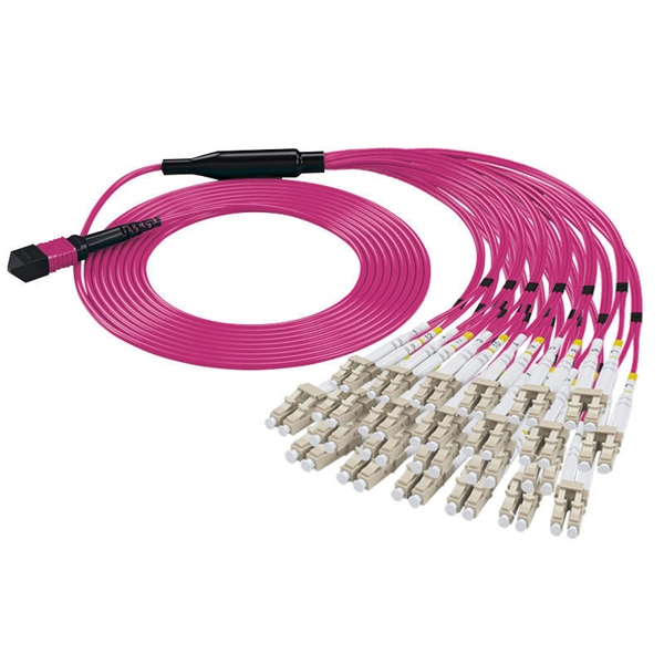
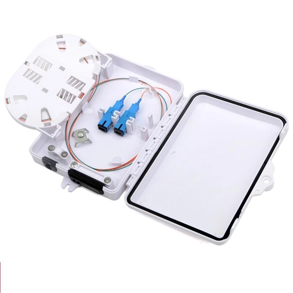
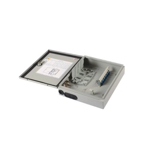
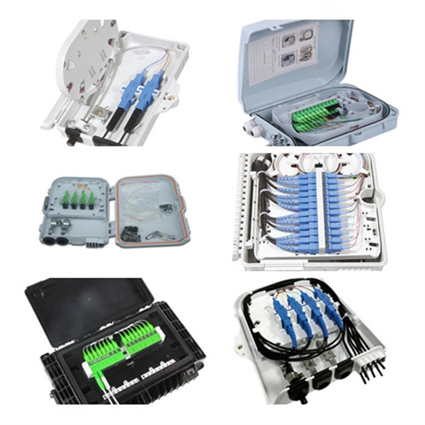
The drop cable connects your home, the patch panel organizes the network, the splice keeps connections seamless, and the optical splitter shares the signal with your neighbors. The fiber drop cable is what makes a true fiber-to-the-home (FTTH) connection possible. It's the final link in the chain that ensures you're getting the full, unfiltered power of fiber internet, not a mix of fiber and older technology. From the street to your living room, every piece of the fiber. To begin, the standard definition of splicing in optical fiber is joining two fiber optic cables together. The other, more common, method of joining fibers is called termination or connectorization. Splicing is most commonly used in the field but has application in cable assembly houses. Infield. In many applications of fiber optics, it is necessary to connect fiber ends (terminations) in some way such that light from one fiber can get into the other fiber without losing too much of its optical power. This creates a permanent and low-loss connection. Both techniques have their advantages and are suited for different applications, but understanding which method to use can greatly impact the network's. Many installations involve splitting the fibers in a cable or dropping a small fiber count cable from a large backbone cable. Backbone cables of 144-288 fibers are common and larger ones are becoming more common too. Drop cables are often only 2-12 fibers, meaning most fibers are continuing.
[PDF]
Instead of fusing one fiber at a time, mass fusion splicing can fuse up to all 12 fibers in one ribbon at once. Many of today's cables with high fiber count involve subunits of 12 fibers each that can be quickly ribbonized. Fiber optic joints or terminations are made two ways: 1) splices which create a permanent joint between the two fibers or 2) connectors that mate two fibers to create a temporary joint and/or connect the fiber to a piece of network gear. Either joining method must have three primary characteristics. Fiber optic splicing is the process of seamlessly joining two single Splicing has a lower optical loss and back-reflection than other terminations, making it the ideal choice for maintaining signal integrity and reliability in fiber optic networks. There are numerous use cases for fiber optic splicing. Through splicing, fiber optic technicians can extend the length of the fiber to make it long enough for use in a required cable run. As. To begin, the standard definition of splicing in optical fiber is joining two fiber optic cables together. The other, more common, method of joining fibers is called termination or connectorization. Splicing is most commonly used in the field but has application in cable assembly houses.
[PDF]
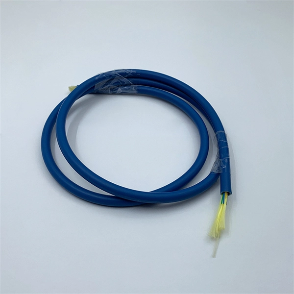
Fiber optic cables can be run anywhere from 2 kilometers to over 100 kilometers without signal regeneration, depending on the cable type and application. Fiber optic cable transmission distance is determined by two primary physical factors that affect signal quality as light travels through the fiber medium. The greater the distance, the greater. In this blog, I will discuss the fiber optic cable distance, the effect factors, how to choose the right fiber optic cables, and how to compare the transmission distances of single-mode and multimode fiber optic cables. Single-mode fiber (SMF) supports distances up to 40-100+ kilometers for standard applications, while multimode fiber (MMF) is typically limited. Fiber optic cables are the backbone of modern communications, enabling high-speed data transfer over vast distances. Unlike traditional copper cables, fiber optic cables use light to transmit data, resulting in faster speeds and greater bandwidth capabilities. Chromatic dispersion This is a key factor affecting single mode fiber distance. While this technology offers higher speeds and longer distances than traditional copper wiring, physical limitations impose distance constraints. Light pulses degrade as they travel over long spans, primarily.
[PDF]
In, a single-mode optical fiber, also known as fundamental- or mono-mode, is an designed to carry only a single of light - the. Modes are the possible solutions o. In 1961, while working at American Optical published a comprehensive theoretical description of single mode fibers in the. At the Corn.
[PDF]
In this post, you'll learn about the differences between one-tailed and two-tailed hypothesis tests and their advantages and disadvantages. I include examples of both types of statistical tests. In my next post, I cover the decision between one and. The design choice of double vertical fins and single vertical fins is not just for appearance considerations, but is deeply affected by the performance and purpose of the aircraft. This article will provide an in-depth analysis of the scientific principles and design logic behind the design of dual. Understanding the difference between one-tailed and two-tailed tests is crucial in determining the directionality of our hypotheses and the significance of our results. Join us as we unravel the intricacies of these tests and discover their applications in educational research. One-tailed tests look for an effect in a specific direction, such as an increase or decrease, while two-tailed tests consider effects in both directions. The alternative hypothesis parameter, commonly referred to as “one-tailed” versus “two-tailed” in statistics, defines the expected direction of the difference between control and treatment groups. In a two-tailed test, we assess whether there is any difference in mean values between the groups. The consequences in this example are extreme, but they illustrate a danger of inappropriate use of a one-tailed test.
[PDF]
A fusion splicer is a specialized device used to join two optical fibers end-to-end through the process of fusion. By aligning the fibers precisely and applying a controlled electric arc, the fusion splicer melts the ends of the fibers, creating a single, continuous fiber. Fusion splicers are essential for creating low-loss, high-performance fiber optic connections in telecom, FTTH, and data center applications. The best splicers offer core alignment, fast splice times, durable designs, and smart features like cloud syncing and automated calibration. This process minimizes. Fiber splicing is the process of permanently joining two fibers together. Unlike fiber connectors, which are designed for easy reconfiguration on cross-connect or patch panels. There are two types of fiber splicing – mechanical splicing and fusion splicing. It is the technique that has the least insertion loss and almost no back reflection, hence ensuring strong connections over a long period. Fiber optic splicers are.
[PDF]
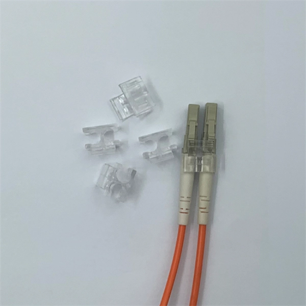
A fiber pigtail is typically a fiber optic cable with one end factory pre-terminated fiber connector and the other exposed fiber. It is usually suitable for field termination using a mechanical or fusion splicer. Executive Summary: A fiber optic pigtail is one of the most commonly specified yet least understood components in structured cabling. Get the wrong connector type, the wrong polish, or skip proper fusion splicing technique—and you're looking at elevated signal loss, increased back reflection, and a. A fiber optic pigtail is a short length of optical fiber —typically 0. The connector end is polished and tested under factory conditions, ensuring low insertion loss and high return loss. The connector end can be linked directly to network equipment, while the exposed end can be spliced to another fiber optic cable. Compared with quick termination or epoxy and polish connections placed on the field. Fiber optic pigtails are short, single, or multi-strand pieces of optical fiber cables with a connector on one end and exposed fiber on the other end. This essential function of pigtail fiber is.
[PDF]
Get the best deals for 940 NM Laser Diode at eBay. We have a great online selection at the lowest prices with Fast & Free shipping on many items!. 940 nm laser diode with a singlmode fiber (Hi1060). Also available with PM option and FBG narrow emission spectrum (scroll down to see all versions and prices) Model 1 is offered with various options such as PM fiber output or FBG (Fiber Bragg Grating). com Skip to content Search for: Home About Laserland Lab Distributors around the World FAQ Page Services Optics Experiment and Basic Teaching Laser Parts Volume Supply High Power Diode Lasers and Laser Bar Array (10W-100W) Laser Module Customization Catalog of Laser. Copyright:Wavespectrum Laser. - All Rights Reserved. 940nm 50mW Powerful Infrared Laser Module TO18 5. 6mm All products have been tested before shipment The product life in more. 6mmTO-18 Use: can be used for the laser gun, night vision, medical and other industries. 940nm 700mW Laser. For nearly 30 years, RPMC Lasers has provided the widest selection of semiconductor laser diode wavelengths and packages for various applications in the Defense, Medical, Industrial, & Research markets. From standard commercial off-the-shelf components to completely Customized Laser Diode.
[PDF]
Unlike a regular diode, the goal for a laser diode is to recombine all carriers in the I region, and produce light. Thus, laser diodes are fabricated using direct band-gap semiconductors.OverviewA laser diode (LD, also injection laser diode or ILD or semiconductor laser or diode laser) is a device similar to a in which a diode pumped directly with electrical current can create. A laser diode is electrically a. The active region of the laser diode is in the intrinsic (I) region, and the carriers (electrons and holes) are pumped into that region from the N and P regions respectivel. Following theoretical treatments of M.G. Bernard, G. Duraffourg, and William P. Dumke in the early 1960s, light emission from a (GaAs) semiconductor diode (a laser diode) was demonstrat.
[PDF]
Diode lasers are compact, solid-state devices that generate coherent light from semiconductor material. They are constructed using materials like gallium arsenide (GaAs) or gallium nitride (GaN). SEM (scanning electron microscope) image of a commercial laser diode with its case and window cut away. The anode connection on the right has been accidentally broken by the case cut process. They operate by applying an electrical current to the semiconductor material, which stimulates the. What is a Laser Diode? A laser diode is a small, solid-state equipment that uses semiconductor material to produce continuous light. The laser can be made up of a single diode or a combination. Laser diodes come in various types, each suited for specific applications. The most common types include: Single-Mode Laser Diodes: Emit a single wavelength of light, ideal for high-precision tasks. VCSEL. The laser diode is a form of semiconductor diode that generates coherent laser light rather than the more usual incoherent light produced by other sources such as LEDs or other emitters, even though some of these produce a narrow band of frequencies. Semiconductor laser diode technology is in. The term LASER stands for Light Amplification by Stimulated Emission of Radiation. It functions similarly to an LED, but the key.
[PDF]
The laser diode market in Kazakhstan is experiencing growth, driven by expanding applications in sectors such as telecommunications, healthcare, and consumer electronics. Laser diodes find use in devices such as optical transmitters, barcode scanners, and laser pointers. Technological advancements. Blue Laser Diodes Market size was valued at USD 245 million in 2024 to USD 370 million by 2032, exhibiting a CAGR of 6. 2% during the forecast period. 7 billion in 2024 and is anticipated to grow at a CAGR of 14. 4% between 2025 to 2034. Rapid proliferation of high-power laser diodes in autonomous vehicle technologies. 744 USD Billion in 2024. The market drivers for the Blue Laser Diodes Market can be influenced by various factors. These may include: Growing Demand in Consumer.
[PDF]