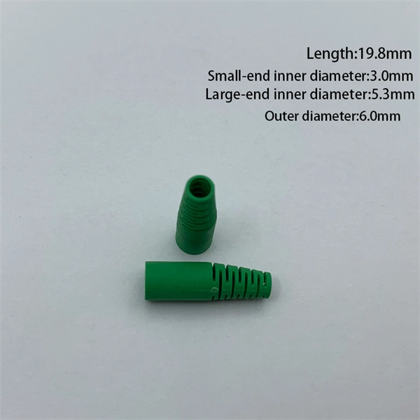
Optical splitters enable a signal on an optical fiber to be distributed among two or more fibers. Since fiber splitters contain no electronics nor require power, they are an integral component and widely used in most fiber-optic networks. A fiber optic splitter is a passive optical component that divides a single incoming optical signal into two or more outgoing signals, or combines multiple incoming signals into one. Unlike active devices (which require power), splitters operate without electricity, relying solely on the physics of. Optical cables, also known as fiber optic cables, consist of thin strands of glass or plastic fibers surrounded by a protective casing. These fibers transmit data as light signals, which are converted into electrical signals at the receiving end. The benefits of optical cables are numerous. A fiber-optic splitter, also known as a beam splitter, is based on a quartz substrate of an integrated waveguide optical power distribution device, similar to a coaxial cable transmission system. Its primary role is in Passive Optical Networks (PON), which are the foundation of. A fiber broadband provider typically determines and overall split ratio for the network, such as 1x32 or 1x64, and uses combinations of splitters to meet that ratio with each PON port. 1x32 splits were common in North America for G-PON architectures. As XGS-PON continues to be adopted, some service.
[PDF]
Optical modulators are used in optical communication systems to encode data onto light waves for transmission through optical fibers. The modulator encodes the data onto the light wave by modifying its amplitude, phase, or frequency. 📦 For purchasing, use the RP Photonics Buyer's Guide for optical modulators. It provides an expert-curated supplier directory, buyer-focused technical background information, and structured selection criteria to support professional procurement decisions. What are Optical Modulators? An optical. Optical modulators are devices that modify the properties of light, such as its amplitude, phase, frequency, or polarization, in response to an external signal. These devices play a crucial role in modern optics and photonics, enabling the manipulation of light for various applications. The beam may be carried over free space, or propagated through an optical waveguide (optical fibre). It acts as the “translator” between the electronic and photonic worlds. They enable the modification of optical wave characteristics such as the intensity, phase, polar-ization, and frequency of light signals. There are basically two types of modulators: bulk and integrated-optic.
[PDF]
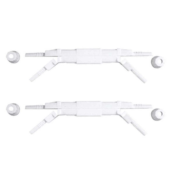
Square D by Schneider Electric offers a unique replacement kit designed to adapt to all brands, different use case scenarios and load type devices such as Load Centers and CSEDs. This kit consists of tw.
[PDF]
Instead of fusing one fiber at a time, mass fusion splicing can fuse up to all 12 fibers in one ribbon at once. Many of today's cables with high fiber count involve subunits of 12 fibers each that can be quickly ribbonized. Fiber optic joints or terminations are made two ways: 1) splices which create a permanent joint between the two fibers or 2) connectors that mate two fibers to create a temporary joint and/or connect the fiber to a piece of network gear. Either joining method must have three primary characteristics. Fiber optic splicing is the process of seamlessly joining two single Splicing has a lower optical loss and back-reflection than other terminations, making it the ideal choice for maintaining signal integrity and reliability in fiber optic networks. There are numerous use cases for fiber optic splicing. Through splicing, fiber optic technicians can extend the length of the fiber to make it long enough for use in a required cable run. As. To begin, the standard definition of splicing in optical fiber is joining two fiber optic cables together. The other, more common, method of joining fibers is called termination or connectorization. Splicing is most commonly used in the field but has application in cable assembly houses.
[PDF]

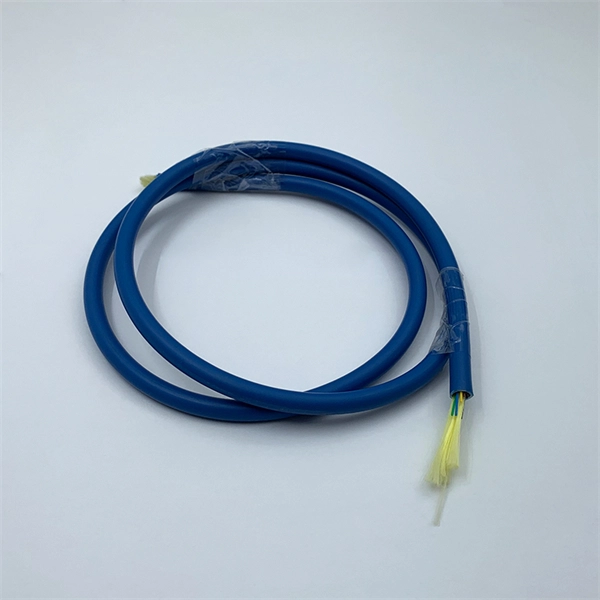
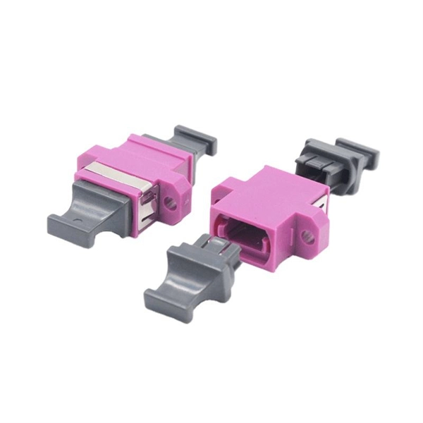
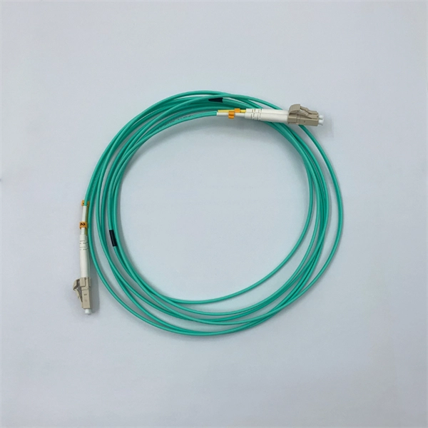
The most commonly used patch cable connectors today include FC, ST, SC, LC, MTRJ, and MPO connector types, as well as newer very small-form-factor (VSFF) CS, SN, and MDC connectors used in high-density, high-speed duplex data center environments. This guide will help you quickly understand the main types of fiber patch cords and how to choose the right solution for your project – and how ZION can support you with stable quality, flexible customization and global supply. What Is a Fiber Optic Patch Cord? A fiber optic patch cord (fiber. An optical fiber patch Cable is a jumper wire used to connect from equipment to an optical fiber cabling link, and it is usually used for the connection between an optical transceiver and a terminal box. It is widely applied in fields such as optical fiber communication systems, optical fiber. Fiber optic patch cords, also known as fiber optic patch cables or fiber jumpers, are indispensable components in modern optical networks. They act as the critical link for interconnecting devices like optical switches, servers, and distribution frames. Behind its slender appearance lies the fusion of core types, connector types, and polish levels, each chosen for a specific application. It is composed of fiber optic cable and fiber connector that fixed at both ends of optical cable, has been widely used in various fields such as fiber optic.
[PDF]
As shown in the figure below, the main cable consists of three conductor wires extending from the top of the motor flat lead extension to the wellhead banded to the production tubing. The ESP cable carries current (amperage) from the motor controller at the surface down to the motor. CAVALCADE™ ESP power cable meets the high-quality standards required for any oil and gas industry specification–even the most challenging unconventional applications–to deliver the electrical requirements of your ESP and to extend system run life. Get cable built with solid copper conductors. Typically, it is banded or clamped to the production tubing from below the wellhead to the ESP unit because it is not designed to support its own weight. It is a specially constructed three-phase power. Levare is one of few artificial lift equipment providers manufacturing the complete ESP system including power cable. The total facilities capacity is approximately 10,000 kilometers (over 6,200 miles) of power and motor lead extension (MLE) cables annually. It is a specially constructed three-phase power cable designed. When performing well interventions, the choice of a suitable cable is critical to ensure well control is maintained while deploying wireline through pressure control equipment (PCE). Depending on the well conditions, many considerations should be taken into account for choosing the best cable.
[PDF]
At the heart of every optical transceiver lie three essential components, often called the “Three Pillars” of optical communication: Laser — generates light. Modulator — encodes data onto the light. Photodiode — decodes light signals back into electrical form. As an essential component of optical fiber communication, optical modules are optoelectronic devices that facilitate the conversion between optical and electrical signals during the transmission process. Operating at the physical layer of the OSI model, optical modules are core devices in optical. An optical module usually consists of an optical transmitting device (TOSA, including a laser), an optical receiving device (ROSA, including a photodetector), functional circuits,main control circuit board (PCBA), housing and optical (electrical) interface and other components. Together, lasers, modulators, and. That is, metal medium communication represented by coaxial cables and network cables is gradually being replaced by optical fiber media. Composition of Optical Modules The optical module, known as Optical Transceiver in. This comprehensive guide breaks down the internal structure, core components (TOSA, ROSA, lasers), and operational mechanisms of SFP optical modules, enriched with technical insights and real-world applications. These modules typically consist of a transmitter, which converts electrical signals into a light signal, and a receiver, which converts the received signal back.
[PDF]
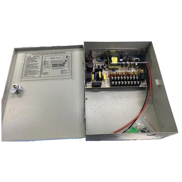
The primary function of a feeder wire is to facilitate bulk power transfer from a central source to a subpanel or a secondary distribution center. An example is the large cable running from the main service panel to a subpanel in a detached garage, basement, or workshop. A main panel and a sub-panel are both important components of an electrical distribution system. It is usually located where the main electrical service enters the building, often on an. Main feeder wires are the arteries of a building's electrical system, designed to safely and efficiently transport a large volume of power from the service entrance to secondary distribution points. They form the backbone of the electrical distribution network, handling the substantial current. An electrical sub panel, also known as a sub distribution board or sub circuit breaker panel, is a smaller secondary panel connected to the main electrical panel in a building. It serves as an extension of the main electrical panel to distribute power to different areas or circuits within a. Distribution board is a safe system designed for house or building that included protective devices, isolator switches, circuit breaker and fuses to safely connect the cables and wires to the sub circuits and final sub circuits including their associated Live (Phase) Neutral and Earth conductors. The distribution box acts as the center of power distribution, distributing electricity to all connected devices.
[PDF]
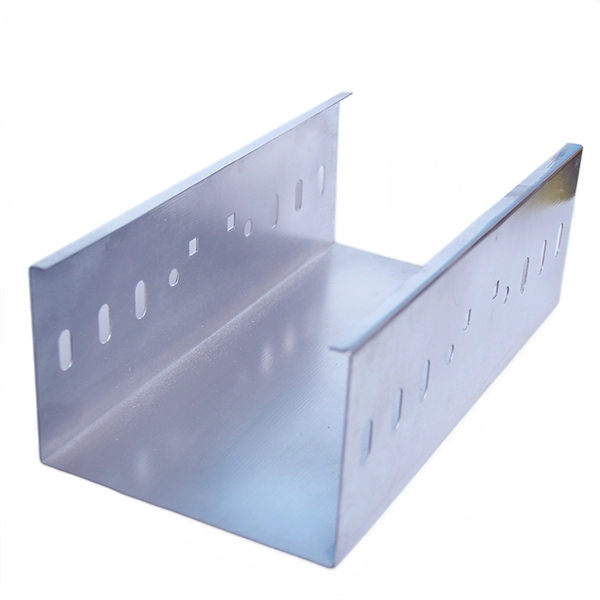
This chart guides how close workers can safely get to energized equipment based on system voltages and other factors, ensuring compliance with safety standards such as NFPA 70E. A distribution box, also known as a distribution board or panel, is the central unit that distributes incoming electrical power to various circuits. Each outgoing line can be individually. Working space: The front clearance, side clearance, and height clearance requirements for electrical equipment that provide a safe area for maintenance, inspections, and other work. Dedicated space: The space equal to the width and depth of electrical equipment in addition to the space extending. The National Electrical Code (NEC) provides comprehensive safety standards for electrical installations, including requirements for electrical panels (main service panels and subpanels or breaker box). NEC Article 408 covers switchboards, switchgear, and Panelboards installation and applications. Electrical clearances set the minimum safe distances for panels, overhead lines, pools, and buried wiring — and ignoring them has real consequences. They would have done better to use an LB or a gutter. The problem is the box has a rated fill and the wire has a bend radius. Maintaining a safe working distance from energized parts in electric power systems is critical to preventing electrical.
[PDF]