BMPT-62 (sometimes called Algerian Terminator in reference to the BMPT Terminator) – A fire support vehicle developed from leftover T-62 tanks and Berezhok turrets. The vehicle was presented at the 60th anniversary parade of Algeria's independence. the BMPT-62 is a fire support fighting vehicle specific to Algeria, often nicknamed locally "Mini Terminator". This is not a standard Sovie. TypeFire Support Combat Vehicle (Tank support combat vehicle) · Place of originIn service2010s–presentUsed byDevelopmentThe concept of the BMPT-62 was born out of 's desire to have a tank support vehicle similar to the Russian "Terminator" (which Algeria also has in active service). The development was carried out. The concept of converting retired T-62 main battle tanks into fire support vehicles emerged from the Algerian Army's logistics and upgrade experience with the Russian-made Berezhok turret system. Algerian engineers.
[PDF]
Explore a vast selection of robust and reliable connectors at Norwegian Electronic Supply AS. Designed for subsea and marine applications, our connectors ensure optimal performance. High-quality fiber cables, connectors, and assemblies for enterprise and infrastructure networks. Fiber connectivity engineered for shock, vibration, temperature extremes, and demanding field. T&G is a leading manufacturer and distributor of connectivity solutions including cables, harnesses, connectors, fiber optic boards, tools, and accessories. of our DNA and is incuded in everything we do. T&G is certified to EN9100 (AS9100), ISO9001 and ISO14001. our customers' needs. Hos oss finner du alt du trenger til ditt fibernett! Fiberworks is a specialized manufacturer in the fiber optic market, offering a variety of products and services. Several functions. One cable | Smart cable solutions. Our selection also includes Huber+Suhner's portfolio of their self-developed connectors for. The M Series connectors meet the highest standards of safety for deep immersion. It is currently used in many applications: from oil and gas industry service to renewable energy generation system and military submarines. The M Series feature a large range of shell styles, layouts or insulator.
[PDF]
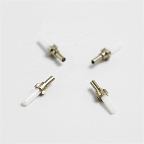
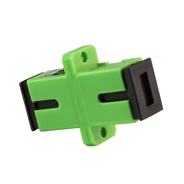
The simplest method: connect two cables pre-connectorized via a coupler (also called an adapter). The coupler aligns the two ferrules of the connectors using a zirconia sleeve. Why connect two fibers? Do you need to extend, repair, or connect two fiber optic cables? There are three methods main ones, each with its advantages and limitations. This article explains when. Optical fiber fast connectors, also known as cold connectors, are becoming increasingly popular due to their ease of use and quick installation. Unlike traditional fiber connectors that require epoxy and polishing, fast connectors use a mechanical splice to join the fibers. Another method is using a mechanical splice which involves aligning and securing the fiber ends with a precision. Fiber optic cables can be connected together using a couple of different methods: 1. This creates a permanent and low-loss connection. Connectors play a crucial role in our daily lives, yet there are some connectors that remain less familiar, such as fiber optic fast connectors. The goal is clean.
[PDF]
There are currently three methods of looking inside a fiber optic connector: (1) Non-destructive X-ray (2) Lossless sonar (3) Destructive cross section These methods help engineers determine the causes and effects of fiber optic connector failures and monitor the connector assembly. There are currently three methods of looking inside a fiber optic connector: (1) Non-destructive X-ray (2) Lossless sonar (3) Destructive cross section These methods help engineers determine the causes and effects of fiber optic connector failures and monitor the connector assembly. Fiber Optic Center offers a unique cross-sectioning service to identify and isolate problems related to fiber optic terminations that would otherwise be invisible. All. There are two major uses for visual inspection of fiber optic connectors. Video microscopes should have ability to record images and some may have ability to analyze connector condition to standards. Look for dirt, contamination, scratches or any other problem. Since connectors are susceptible to damage that is not immediately obvious to the naked eye—the inspection phase is vital. When proceeding with the inspection of connectors, there are two main components to inspect: the connector itself and the ferrule. With the press of a single button, FOCIS Flex auto-focuses, captures and centers the end-face image, applies Pass/Fail rules, displays image and Pass/Fail results, saves results internally and/or wirelessly transfers data to a.
[PDF]
EIA/TIA 568 B allows any fiber optic connector as long as it has a FOCIS (Fiber Optic Connector Intermateability Standard) document behind it. Fiber optic cold connection, also known as mechanical splicing, is a widely used method of connecting optical fibers in a network. Unlike fusion splicing, which uses heat to join two optical fibers together, cold connection uses mechanical means to create a stable and low-loss connection. Unlike fiber splicing, which is permanent, connectors allow for easy connection and disconnection of cables, making them ideal for maintenance and flexibility in. Fiber optic joints or terminations are made two ways: 1) splices which create a permanent joint between the two fibers or 2) connectors that mate two fibers to create a temporary joint and/or connect the fiber to a piece of network gear. These terminations must be of the right style, installed in a. Fiber termination refers to the process of preparing the end of a fiber optic cable to connect to another fiber, a device, or a network. Proper termination is essential for ensuring optimal performance, reducing signal loss, and maintaining the durability of the connection. Since the introduction of fiber optic technology decades ago, a variety of connector types have been.
[PDF]
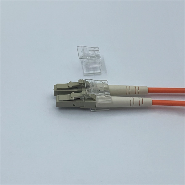
Fiber optic connectors can be categorized according to different standards such as utilization, fiber count, fiber mode, and transmission method. They are also divided into single-mode and multimode types based on their distinct characteristics. The fiber connector types, sometimes referred to as terminations, link fiber optic cables together through terminals, switches, adapters, and patch panels, by bridging the gap between their internal glass fibers that transmit the data down the length of the cable. And based on the connector construction, LC connector also can be divided into LC duplex and simplex connector. a single mode fiber (SMF). And it has a “square shaped” connector body, which is the source of name “square connector”. Due. Fiber optic connectors, according to the different transmission media, can be divided into common silicon-based fiber single-mode and multimode connectors, and other such as plastic as the transmission medium of fiber optic connectors; according to the connector, structure form can be divided into:. A fiber optic connector is a mechanical device used to align and join optical fibers, enabling light to pass through with minimal loss. Simplex vs duplex fiber connectors, single mode vs multimode fiber connectors, what's the difference? This article will explain the above to you.
[PDF]
Passive media components such as cables, cable splices, and connectors cause attenuation. Although attenuation is significantly lower for optical fiber than for other media, it still occurs in both multimode and single-mode transmissions. Two fundamental mechanisms cause attenuation inside the fiber itself: absorption and scattering. These are intrinsic to the glass, meaning they exist even in a perfectly manufactured, perfectly installed fiber. Scattering is the bigger factor at the wavelengths most networks use. The silica glass. Optical attenuation is the gradual loss of flux (light intensity) as an optical signal travels through a fiber. Measured in decibels (dB), it's the logarithmic ratio of the output power to the input power. Every network has a "loss budget". F iber optic networks rely on the efficient transmission of light signals to deliver high-speed data over long distances. However, various factors can cause signal degradation, leading to performance issues and reduced network reliability. You may see slower speeds and less steady connections when signal loss goes up. Things like impurities in the fiber core and reflections at the core-cladding edge cause this drop. This can be due to a variety of factors: scattering and absorption, intrinsic. Signal attenuation in fiber optics is a key concept in telecommunications. It affects how far a signal can travel without losing.
[PDF]
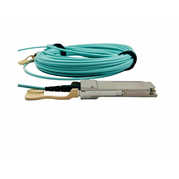
The QSFP28 transceiver provides 100GBase-BX throughput up to 20km over single-mode fiber (SMF) using a wavelength of 1310nmTx/1280nmRx via an LC connector. This bidirectional unit must be used with another transceiver or network appliance of complimenting wavelengths. Whether it's building a network or upgrading an existing network, the Cisco® QSFP-100G-B20U4-I and QSFP-100G-B20D4-I transceivers provide 100G connectivity for platforms at up to 20km on single SMF (Single Mode Fiber). This. The QSFP-100G modules are our latest generation of 100G transceiver modules solution based on a QSFP form factor. Table 1 describes the Cisco QSFP-100G portfolio. Cisco QSFP-100G Portfolio The Cisco 100GBASE-SR4-S QSFP Module supports link lengths of up to 70m. To meet the demand for long-distance transmission in scenarios where optical fiber resources are scarce in edge access networks, Walsun has launched the 100G QSFP28 ZR4 BIDI product, and will demonstrate 100G 80km single-fiber bidirectional service transmission at OFC 2024. 66nm-RX) via an LC. NEC's 100G QSFP28 BiDi optical transceiver enables the transmission and reception of 100Gb/s high-speed data over a single optical fiber. By enabling bidirectional transmission over a single fiber, this module enhances fiber utilization efficiency and can reduce fiber costs. ZR4 BiDi, using four.
[PDF]
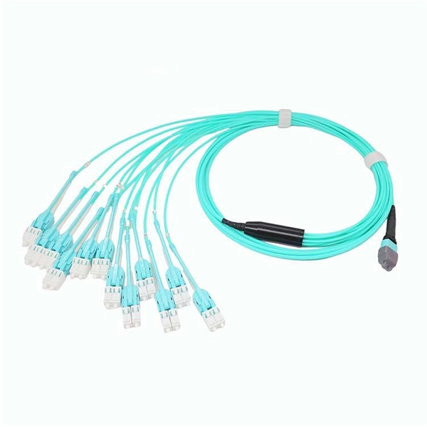
Instead of fusing one fiber at a time, mass fusion splicing can fuse up to all 12 fibers in one ribbon at once. Many of today's cables with high fiber count involve subunits of 12 fibers each that can be quickly ribbonized. Fiber optic joints or terminations are made two ways: 1) splices which create a permanent joint between the two fibers or 2) connectors that mate two fibers to create a temporary joint and/or connect the fiber to a piece of network gear. Either joining method must have three primary characteristics. Fiber optic splicing is the process of seamlessly joining two single Splicing has a lower optical loss and back-reflection than other terminations, making it the ideal choice for maintaining signal integrity and reliability in fiber optic networks. There are numerous use cases for fiber optic splicing. Through splicing, fiber optic technicians can extend the length of the fiber to make it long enough for use in a required cable run. As. To begin, the standard definition of splicing in optical fiber is joining two fiber optic cables together. The other, more common, method of joining fibers is called termination or connectorization. Splicing is most commonly used in the field but has application in cable assembly houses.
[PDF]
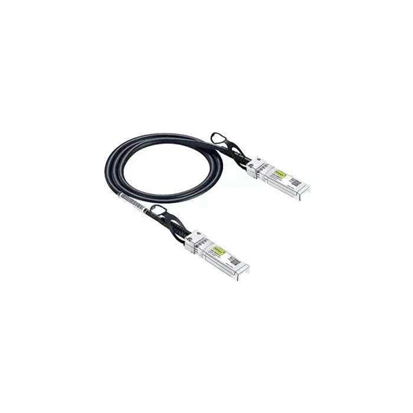
To connect an optical cable to an SFP module, use the appropriate patch cord (e., LC-LC, SC-LC, etc. The patch cord must match the fibre type – single-mode or multi-mode. Once connected, verify that the port activity indicator is on and run diagnostic commands to check the. Small Form-factor Pluggable modules (SFP module) are the workhorses of modern network connectivity, enabling flexible fiber optic or copper links between switches, routers, firewalls, and servers. Whether you're upgrading bandwidth, replacing a faulty unit, or reconfiguring your topology, knowing. Connecting your fiber optic cable to an SFP (Small Form-factor Pluggable) module can seem daunting if you're unfamiliar with networking hardware. However, with a bit of guidance, the process is straightforward. Remove the dust caps from the SFP module and the fiber optic cable. Today, we will discuss the best methods to connect SFP to fiber optic patch cables. To connect a fiber optic cable to SFP optical module, first ensure the SFP is fully inserted into the network port until it "clicks", then remove the dust caps from both the SFP and the LC fiber optic connector. Laser Compliance The fiber-optic SFP+ / SFP28 modules contain a laser that is classified as a “Class 1 Laser Product” in accordance with US FDA regulations and the IEC 60825-1. The product does not emit hazardous laser radiation. The module is fully seated when you hear a click. (SFP+ and SFP28.
[PDF]
This paper discusses some practical aspects of implementing single-pole tripping schemes in transmission-line protection. Implementation and techniques will vary in the design of protective relaying systems that i.
[PDF]
Can two switches with fiber ports be directly connected through fiber ports? The answer is yes. The connection between two or more Ethernet switches in a certain way (Uplink port, etc. ) is. If you have multiple Ethernet switches that need to be connected over long distances, fiber is obviously a preferred choice. Moreover, when it comes to bandwidth, no currently available technology is better than single-mode fiber. ) is called the cascade. I need to connect a single 3750G - 48 ports switch to a single 2960 - 48 ports switch and it needs to be through a fiber. So, PCs connected to one switch would reach the PCs from the other switch. Well, I. Other than entry level network switches, most of today's network switches include one or more GiBC (Gigabit Converter) or SFP (Small Form-factor Pluggable) slots. SFP modules insert into these slots and and require two strands of fiber, typically duplex Using multi mode fiber (for runs under 1000. Fiber optic cabling is increasingly used to connect network switches and other datacom equipment, especially in long-distance and mission-critical applications. Fiber provides: Increased internet signal bandwidth. Most modern fiber-enabled network switches require an SFP transceiver module. I have an issue when connecting two switches with fiber. The switches connect as expected when in the same room and connected using 1m or 3m patch cables. This is where it gets strange.
[PDF]
This paper proposes a mathematical model for busbars used within a high current power supply. The obtained thermal model can be used to analyse the thermal behaviour of busbars in steady-state conditions at different values of the electric current, cross-section and length. Improving surface temperature measurement of the power cable and insulated busbar using the heat insulated layer Abstract The surface temperature measurement is susceptible to the surrounding air for the cable or the insulated busbar laid in free air. Therefore, an approach for improving their. The thermal analysis takes into account the heat conduction and convection of a copper busbar system used to supply a test bench with high currents in order to check the electro-thermal behaviour of power circuit breakers during overload and short circuit conditions. This paper proposes a. Current is supplied via bus bars or wire bonding in power supply lines for power electronics devices such as inverters. Because inverters and similar devices operate with PWM carrier frequencies of several kHz, high-frequency current flows in their bus bars. Influences from the skin effect cannot.
[PDF]
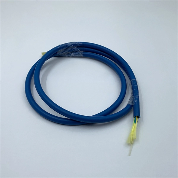
Fiber optic patch cables are ideal for supporting high speed telecommunication network fiber applications. They are manufactured and tested in compliance with TIA 604 (FOCIS), IEC 61754 and YD/T industry s.
[PDF]
Positive busbars, which collect all positive connections. Key Steps: When wiring a pair of 12V busbars, connect the positive terminal of each load to a stud on the positive busbar and their negative terminal to a stud on the negative busbar. 5' above batteries on inside of cockpit combing below decks. Install one new positive bus bar beside the negative one separated by about two inches 3. Positive and negative busbars are physically identical apart from the red/black colours used by some manufacturers to visually differentiate between. A Complete Guide to Battery Terminal Connector Types The store will not work correctly in the case when cookies are disabled. JavaScript seems to be disabled in your browser. For the best experience on our site, be sure to turn on Javascript in your browser. Skip to Content Blog Sign In Create an. This image illustrates a standard car battery with top post terminals and labeled connectors for the positive (+) and negative (–) ends, emphasizing safe and correct installation. A battery terminal connector is a fitting or clamp that attaches to a battery's terminal to connect a cable. In other. Both positive and negative terminals are the soul of the electrical system of the car, allowing the engine to start while keeping other components running. The catch? Mix-up or loose connection can cause electrical failure, drained batteries, and damage to wiring. This blog guides you how the two.
[PDF]